

414
Digital Electronics
Q 0
FF0
J
K
(a)
Q 1
FF1
J
K
Q 2
FF2
J
K
Q 3
FF3
J
K
1
Clock
Q 0
Q 1
Q 2
Q 3
1
2
3
4
5
6
7
8
9 10 1 1 12 13 14 15
16
Clock-Input
Q 0 -Output
Q 1 -Output
Q 2 -Output
Q 3 -Output
(b)
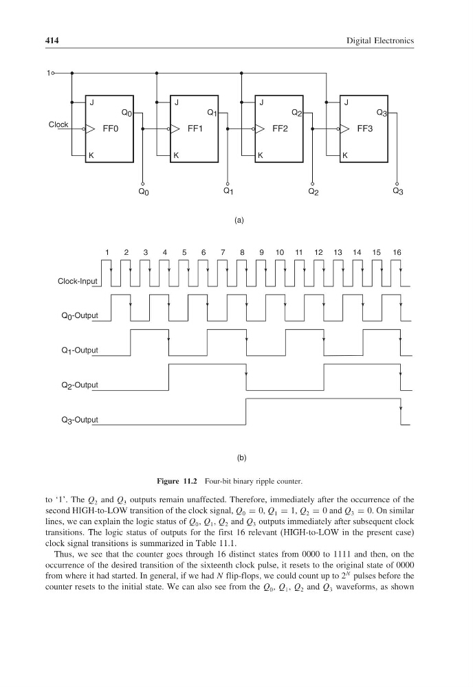
Figure 11.2 Four-bit binary ripple counter.
to ‘1’. The Q 2 and Q 3 outputs remain unaffected. Therefore, immediately after the occurrence of the
second HIGH-to-LOW transition of the clock signal, Q 0 = 0, Q 1 = 1, Q 2 = 0 and Q 3 = 0. On similar
lines, we can explain the logic status of Q 0 , Q 1 , Q 2 and Q 3 outputs immediately after subsequent clock
transitions. The logic status of outputs for the first 16 relevant (HIGH-to-LOW in the present case)
clock signal transitions is summarized in Table 11.1.
Thus, we see that the counter goes through 16 distinct states from 0000 to 1111 and then, on the
occurrence of the desired transition of the sixteenth clock pulse, it resets to the original state of 0000
from where it had started. In general, if we had N flip-flops, we could count up to 2
N pulses before the
counter resets to the initial state. We can also see from the Q 0 , Q 1 , Q 2 and Q 3 waveforms, as shown
Digital Electronics
Q 0
FF0
J
K
(a)
Q 1
FF1
J
K
Q 2
FF2
J
K
Q 3
FF3
J
K
1
Clock
Q 0
Q 1
Q 2
Q 3
1
2
3
4
5
6
7
8
9 10 1 1 12 13 14 15
16
Clock-Input
Q 0 -Output
Q 1 -Output
Q 2 -Output
Q 3 -Output
(b)
Figure 11.2 Four-bit binary ripple counter.
to ‘1’. The Q 2 and Q 3 outputs remain unaffected. Therefore, immediately after the occurrence of the
second HIGH-to-LOW transition of the clock signal, Q 0 = 0, Q 1 = 1, Q 2 = 0 and Q 3 = 0. On similar
lines, we can explain the logic status of Q 0 , Q 1 , Q 2 and Q 3 outputs immediately after subsequent clock
transitions. The logic status of outputs for the first 16 relevant (HIGH-to-LOW in the present case)
clock signal transitions is summarized in Table 11.1.
Thus, we see that the counter goes through 16 distinct states from 0000 to 1111 and then, on the
occurrence of the desired transition of the sixteenth clock pulse, it resets to the original state of 0000
from where it had started. In general, if we had N flip-flops, we could count up to 2
N pulses before the
counter resets to the initial state. We can also see from the Q 0 , Q 1 , Q 2 and Q 3 waveforms, as shown