

398
Digital Electronics
Enable
D
To-other
D-Latches
Q
–
Q
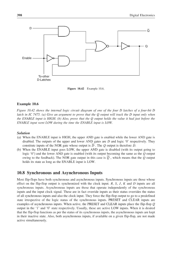
Figure 10.42 Example 10.6.
Example 10.6
Figure 10.42 shows the internal logic circuit diagram of one of the four D latches of a four-bit D
latch in IC 7475. (a) Give an argument to prove that the Q output will track the D input only when
the ENABLE input is HIGH. (b) Also, prove that the Q output holds the value it had just before the
ENABLE input went LOW during the time the ENABLE input is LOW.
Solution
(a) When the ENABLE input is HIGH, the upper AND gate is enabled while the lower AND gate is
disabled. The outputs of the upper and lower AND gates are D and logic ‘0’ respectively. They
constitute inputs of the NOR gate whose output is D . The Q output is therefore D.
(b) When the ENABLE input goes LOW, the upper AND gate is disabled (with its output going to
logic ‘0’) and the lower AND gate is enabled (with its output becoming the same as the Q output
owing to the feedback). The NOR gate output in this case is Q , which means that the Q output
holds its state as long as the ENABLE input is LOW.
10.8 Synchronous and Asynchronous Inputs
Most flip-flops have both synchronous and asynchronous inputs. Synchronous inputs are those whose
effect on the flip-flop output is synchronized with the clock input. R, S, J , K and D inputs are all
synchronous inputs. Asynchronous inputs are those that operate independently of the synchronous
inputs and the input clock signal. These are in fact override inputs as their status overrides the status
of all synchronous inputs and also the clock input. They force the flip-flop output to go to a predefined
state irrespective of the logic status of the synchronous inputs. PRESET and CLEAR inputs are
examples of asynchronous inputs. When active, the PRESET and CLEAR inputs place the flip-flop Q
output in the ‘1’ and ‘0’ state respectively. Usually, these are active LOW inputs. When it is desired
that the flip-flop functions as per the status of its synchronous inputs, the asynchronous inputs are kept
in their inactive state. Also, both asynchronous inputs, if available on a given flip-flop, are not made
active simultaneously.
Digital Electronics
Enable
D
To-other
D-Latches
Q
–
Q
Figure 10.42 Example 10.6.
Example 10.6
Figure 10.42 shows the internal logic circuit diagram of one of the four D latches of a four-bit D
latch in IC 7475. (a) Give an argument to prove that the Q output will track the D input only when
the ENABLE input is HIGH. (b) Also, prove that the Q output holds the value it had just before the
ENABLE input went LOW during the time the ENABLE input is LOW.
Solution
(a) When the ENABLE input is HIGH, the upper AND gate is enabled while the lower AND gate is
disabled. The outputs of the upper and lower AND gates are D and logic ‘0’ respectively. They
constitute inputs of the NOR gate whose output is D . The Q output is therefore D.
(b) When the ENABLE input goes LOW, the upper AND gate is disabled (with its output going to
logic ‘0’) and the lower AND gate is enabled (with its output becoming the same as the Q output
owing to the feedback). The NOR gate output in this case is Q , which means that the Q output
holds its state as long as the ENABLE input is LOW.
10.8 Synchronous and Asynchronous Inputs
Most flip-flops have both synchronous and asynchronous inputs. Synchronous inputs are those whose
effect on the flip-flop output is synchronized with the clock input. R, S, J , K and D inputs are all
synchronous inputs. Asynchronous inputs are those that operate independently of the synchronous
inputs and the input clock signal. These are in fact override inputs as their status overrides the status
of all synchronous inputs and also the clock input. They force the flip-flop output to go to a predefined
state irrespective of the logic status of the synchronous inputs. PRESET and CLEAR inputs are
examples of asynchronous inputs. When active, the PRESET and CLEAR inputs place the flip-flop Q
output in the ‘1’ and ‘0’ state respectively. Usually, these are active LOW inputs. When it is desired
that the flip-flop functions as per the status of its synchronous inputs, the asynchronous inputs are kept
in their inactive state. Also, both asynchronous inputs, if available on a given flip-flop, are not made
active simultaneously.