

Flip-Flops and Related Devices
381
S
Q
R
Q
–
FF
Clk
(c)
Figure 10.22 (continued).
10.4 Level-Triggered and Edge-Triggered Flip-Flops
In a level-triggered flip-flop, the output responds to the data present at the inputs during the time the
clock pulse level is HIGH (or LOW). That is, any changes at the input during the time the clock is active
(HIGH or LOW) are reflected at the output as per its function table. The clocked R-S flip-flop described
in the preceding paragraphs is a level-triggered flip-flop that is active when the clock is HIGH.
In an edge-triggered flip-flop, the output responds to the data at the inputs only on LOW-to-HIGH
or HIGH-to-LOW transition of the clock signal. The flip-flop in the two cases is referred to as positive
edge triggered and negative edge triggered respectively. Any changes in the input during the time
the clock pulse is HIGH (or LOW) do not have any effect on the output. In the case of an edgetriggered flip-flop, an edge detector circuit transforms the clock input into a very narrow pulse that is
a few nanoseconds wide. This narrow pulse coincides with either LOW-to-HIGH or HIGH-to-LOW
transition of the clock input, depending upon whether it is a positive edge-triggered flip-flop or a
negative edge-triggered flip-flop. This pulse is so narrow that the operation of the flip–flop can be
considered to have occurred on the edge itself.
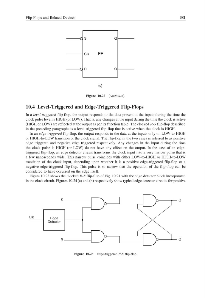
Figure 10.23 shows the clocked R-S flip-flop of Fig. 10.21 with the edge detector block incorporated
in the clock circuit. Figures 10.24 (a) and (b) respectively show typical edge detector circuits for positive
S
Q
Q
—
R
Clk
Edge
Detector
Figure 10.23 Edge-triggered R-S flip-flop.
381
S
Q
R
Q
–
FF
Clk
(c)
Figure 10.22 (continued).
10.4 Level-Triggered and Edge-Triggered Flip-Flops
In a level-triggered flip-flop, the output responds to the data present at the inputs during the time the
clock pulse level is HIGH (or LOW). That is, any changes at the input during the time the clock is active
(HIGH or LOW) are reflected at the output as per its function table. The clocked R-S flip-flop described
in the preceding paragraphs is a level-triggered flip-flop that is active when the clock is HIGH.
In an edge-triggered flip-flop, the output responds to the data at the inputs only on LOW-to-HIGH
or HIGH-to-LOW transition of the clock signal. The flip-flop in the two cases is referred to as positive
edge triggered and negative edge triggered respectively. Any changes in the input during the time
the clock pulse is HIGH (or LOW) do not have any effect on the output. In the case of an edgetriggered flip-flop, an edge detector circuit transforms the clock input into a very narrow pulse that is
a few nanoseconds wide. This narrow pulse coincides with either LOW-to-HIGH or HIGH-to-LOW
transition of the clock input, depending upon whether it is a positive edge-triggered flip-flop or a
negative edge-triggered flip-flop. This pulse is so narrow that the operation of the flip–flop can be
considered to have occurred on the edge itself.
Figure 10.23 shows the clocked R-S flip-flop of Fig. 10.21 with the edge detector block incorporated
in the clock circuit. Figures 10.24 (a) and (b) respectively show typical edge detector circuits for positive
S
Q
Q
—
R
Clk
Edge
Detector
Figure 10.23 Edge-triggered R-S flip-flop.