

Flip-Flops and Related Devices
375
S
Q
Q
—
R
2
1
S
R
Q
Q
—
Operation
Mode
No change
SET
RESET
Forbidden
S
1
0
1
0
R
1
1
0
0
Q n+1
Qn
1
0
—
(a)
(b)
(c)
RS
FF
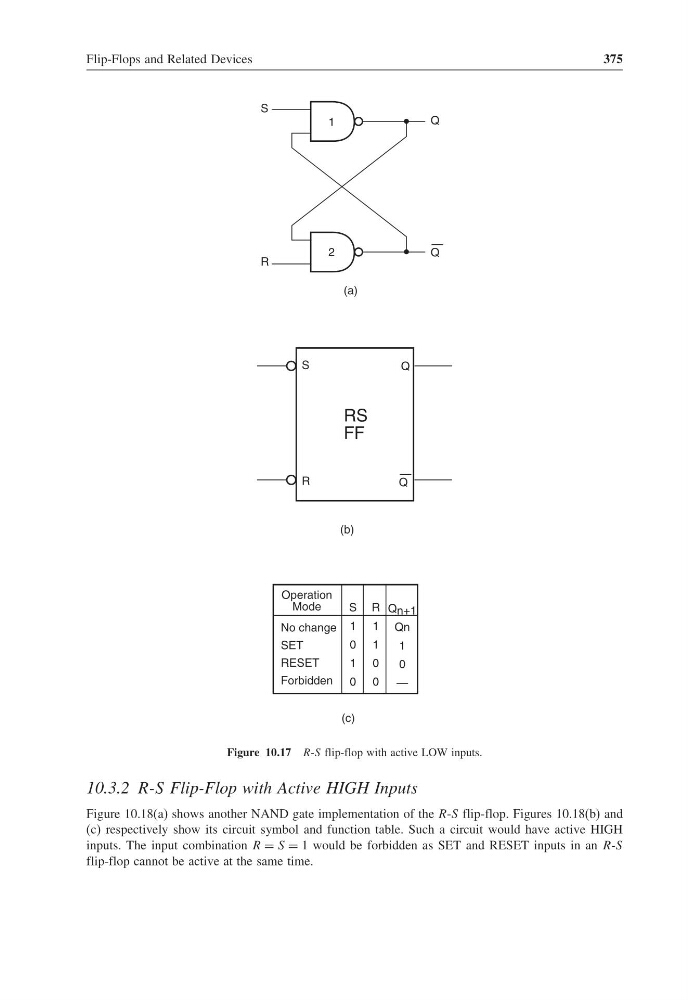
Figure 10.17 R-S flip-flop with active LOW inputs.
10.3.2 R-S Flip-Flop with Active HIGH Inputs
Figure 10.18(a) shows another NAND gate implementation of the R-S flip-flop. Figures 10.18(b) and
(c) respectively show its circuit symbol and function table. Such a circuit would have active HIGH
inputs. The input combination R = S = 1 would be forbidden as SET and RESET inputs in an R-S
flip-flop cannot be active at the same time.
375
S
Q
Q
—
R
2
1
S
R
Q
Q
—
Operation
Mode
No change
SET
RESET
Forbidden
S
1
0
1
0
R
1
1
0
0
Q n+1
Qn
1
0
—
(a)
(b)
(c)
RS
FF
Figure 10.17 R-S flip-flop with active LOW inputs.
10.3.2 R-S Flip-Flop with Active HIGH Inputs
Figure 10.18(a) shows another NAND gate implementation of the R-S flip-flop. Figures 10.18(b) and
(c) respectively show its circuit symbol and function table. Such a circuit would have active HIGH
inputs. The input combination R = S = 1 would be forbidden as SET and RESET inputs in an R-S
flip-flop cannot be active at the same time.