

Flip-Flops and Related Devices
373
4,8
6,7
3
2
1
5
V CC
0.01
Trigger Input
555
10K
Output
0.01
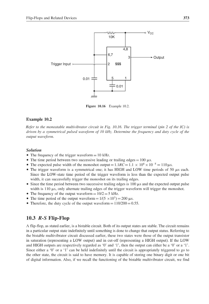
Figure 10.16 Example 10.2.
Example 10.2
Refer to the monostable multivibrator circuit in Fig. 10.16. The trigger terminal (pin 2 of the IC) is
driven by a symmetrical pulsed waveform of 10 kHz. Determine the frequency and duty cycle of the
output waveform.
Solution
• The frequency of the trigger waveform = 10 kHz.
• The time period between two successive leading or trailing edges = 100 s.
• The expected pulse width of the monoshot output = 1.1RC = 1.1 × 10
4
× 10
−8
= 110 s.
• The trigger waveform is a symmetrical one; it has HIGH and LOW time periods of 50 s each.
Since the LOW-state time period of the trigger waveform is less than the expected output pulse
width, it can successfully trigger the monoshot on its trailing edges.
• Since the time period between two successive trailing edges is 100 s and the expected output pulse
width is 110 s, only alternate trailing edges of the trigger waveform will trigger the monoshot.
• The frequency of the output waveform = 10/2 = 5 kHz.
• The time period of the output waveform = 1/(5 ×10
3 = 200 s.
• Therefore, the duty cycle of the output waveform = 110/200 = 0.55.
10.3 R-S Flip-Flop
A flip-flop, as stated earlier, is a bistable circuit. Both of its output states are stable. The circuit remains
in a particular output state indefinitely until something is done to change that output status. Referring to
the bistable multivibrator circuit discussed earlier, these two states were those of the output transistor
in saturation (representing a LOW output) and in cut-off (representing a HIGH output). If the LOW
and HIGH outputs are respectively regarded as ‘0’ and ‘1’, then the output can either be a ‘0’ or a ‘1’.
Since either a ‘0’ or a ‘1’ can be held indefinitely until the circuit is appropriately triggered to go to
the other state, the circuit is said to have memory. It is capable of storing one binary digit or one bit
of digital information. Also, if we recall the functioning of the bistable multivibrator circuit, we find
373
4,8
6,7
3
2
1
5
V CC
0.01
Trigger Input
555
10K
Output
0.01
Figure 10.16 Example 10.2.
Example 10.2
Refer to the monostable multivibrator circuit in Fig. 10.16. The trigger terminal (pin 2 of the IC) is
driven by a symmetrical pulsed waveform of 10 kHz. Determine the frequency and duty cycle of the
output waveform.
Solution
• The frequency of the trigger waveform = 10 kHz.
• The time period between two successive leading or trailing edges = 100 s.
• The expected pulse width of the monoshot output = 1.1RC = 1.1 × 10
4
× 10
−8
= 110 s.
• The trigger waveform is a symmetrical one; it has HIGH and LOW time periods of 50 s each.
Since the LOW-state time period of the trigger waveform is less than the expected output pulse
width, it can successfully trigger the monoshot on its trailing edges.
• Since the time period between two successive trailing edges is 100 s and the expected output pulse
width is 110 s, only alternate trailing edges of the trigger waveform will trigger the monoshot.
• The frequency of the output waveform = 10/2 = 5 kHz.
• The time period of the output waveform = 1/(5 ×10
3 = 200 s.
• Therefore, the duty cycle of the output waveform = 110/200 = 0.55.
10.3 R-S Flip-Flop
A flip-flop, as stated earlier, is a bistable circuit. Both of its output states are stable. The circuit remains
in a particular output state indefinitely until something is done to change that output status. Referring to
the bistable multivibrator circuit discussed earlier, these two states were those of the output transistor
in saturation (representing a LOW output) and in cut-off (representing a HIGH output). If the LOW
and HIGH outputs are respectively regarded as ‘0’ and ‘1’, then the output can either be a ‘0’ or a ‘1’.
Since either a ‘0’ or a ‘1’ can be held indefinitely until the circuit is appropriately triggered to go to
the other state, the circuit is said to have memory. It is capable of storing one binary digit or one bit
of digital information. Also, if we recall the functioning of the bistable multivibrator circuit, we find