

372
Digital Electronics
0.01
1
5
555
2, 6
8
3
7
4
0.01 F
µ
14.5K
14.5K
1ms
1ms
(a)
(b)
+Vcc
v o
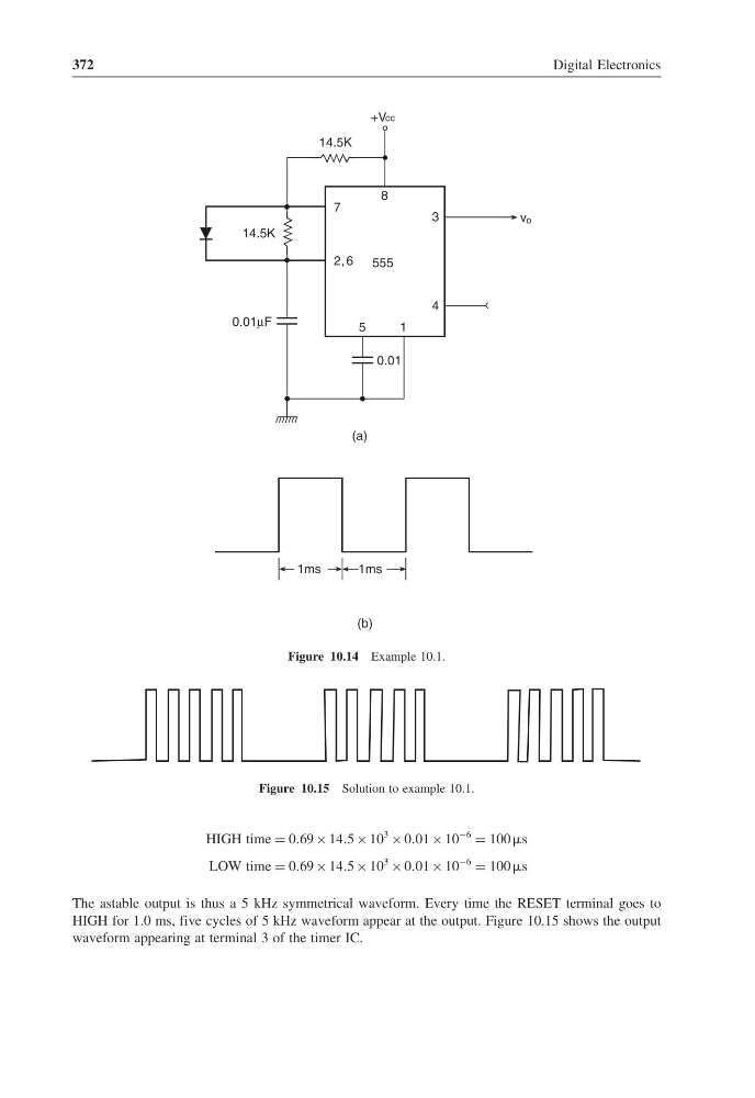
Figure 10.14 Example 10.1.
Figure 10.15 Solution to example 10.1.
HIGH time = 069 × 145 × 10
3 × 001 × 10
−6 = 100 s
LOW time = 069 × 145 × 10
3 × 001 × 10
−6 = 100 s
The astable output is thus a 5 kHz symmetrical waveform. Every time the RESET terminal goes to
HIGH for 1.0 ms, five cycles of 5 kHz waveform appear at the output. Figure 10.15 shows the output
waveform appearing at terminal 3 of the timer IC.
Digital Electronics
0.01
1
5
555
2, 6
8
3
7
4
0.01 F
µ
14.5K
14.5K
1ms
1ms
(a)
(b)
+Vcc
v o
Figure 10.14 Example 10.1.
Figure 10.15 Solution to example 10.1.
HIGH time = 069 × 145 × 10
3 × 001 × 10
−6 = 100 s
LOW time = 069 × 145 × 10
3 × 001 × 10
−6 = 100 s
The astable output is thus a 5 kHz symmetrical waveform. Every time the RESET terminal goes to
HIGH for 1.0 ms, five cycles of 5 kHz waveform appear at the output. Figure 10.15 shows the output
waveform appearing at terminal 3 of the timer IC.