

Flip-Flops and Related Devices
371
R
6, 7
555
8
4
2
Q
R 2
R 3
V CC
C 1
Trigger
I/P
After
differentiator
Trigger
I/P
V CC
0
V CC
C
0.01
5
1
3
D
R 1
–0.7
V CC
0
At Pin-2
0
(a)
(b)
v o
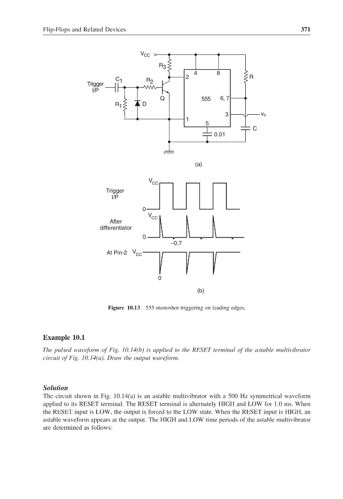
Figure 10.13 555 monoshot triggering on leading edges.
Example 10.1
The pulsed waveform of Fig. 10.14(b) is applied to the RESET terminal of the astable multivibrator
circuit of Fig. 10.14(a). Draw the output waveform.
Solution
The circuit shown in Fig. 10.14(a) is an astable multivibrator with a 500 Hz symmetrical waveform
applied to its RESET terminal. The RESET terminal is alternately HIGH and LOW for 1.0 ms. When
the RESET input is LOW, the output is forced to the LOW state. When the RESET input is HIGH, an
astable waveform appears at the output. The HIGH and LOW time periods of the astable multivibrator
are determined as follows:
371
R
6, 7
555
8
4
2
Q
R 2
R 3
V CC
C 1
Trigger
I/P
After
differentiator
Trigger
I/P
V CC
0
V CC
C
0.01
5
1
3
D
R 1
–0.7
V CC
0
At Pin-2
0
(a)
(b)
v o
Figure 10.13 555 monoshot triggering on leading edges.
Example 10.1
The pulsed waveform of Fig. 10.14(b) is applied to the RESET terminal of the astable multivibrator
circuit of Fig. 10.14(a). Draw the output waveform.
Solution
The circuit shown in Fig. 10.14(a) is an astable multivibrator with a 500 Hz symmetrical waveform
applied to its RESET terminal. The RESET terminal is alternately HIGH and LOW for 1.0 ms. When
the RESET input is LOW, the output is forced to the LOW state. When the RESET input is HIGH, an
astable waveform appears at the output. The HIGH and LOW time periods of the astable multivibrator
are determined as follows: