

Flip-Flops and Related Devices
369
555
+V CC
4
8
6,7
3
5
1
2
+V CC
Trigger
input
v o
Output
—V CC
V C
2
3
t
t
t
R
C
(a)
(b)
v o
v c
Trigger
0.01
T
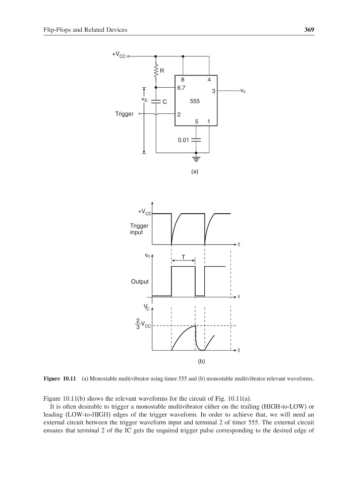
Figure 10.11 (a) Monostable multivibrator using timer 555 and (b) monostable multivibrator relevant waveforms.
Figure 10.11(b) shows the relevant waveforms for the circuit of Fig. 10.11(a).
It is often desirable to trigger a monostable multivibrator either on the trailing (HIGH-to-LOW) or
leading (LOW-to-HIGH) edges of the trigger waveform. In order to achieve that, we will need an
external circuit between the trigger waveform input and terminal 2 of timer 555. The external circuit
ensures that terminal 2 of the IC gets the required trigger pulse corresponding to the desired edge of
369
555
+V CC
4
8
6,7
3
5
1
2
+V CC
Trigger
input
v o
Output
—V CC
V C
2
3
t
t
t
R
C
(a)
(b)
v o
v c
Trigger
0.01
T
Figure 10.11 (a) Monostable multivibrator using timer 555 and (b) monostable multivibrator relevant waveforms.
Figure 10.11(b) shows the relevant waveforms for the circuit of Fig. 10.11(a).
It is often desirable to trigger a monostable multivibrator either on the trailing (HIGH-to-LOW) or
leading (LOW-to-HIGH) edges of the trigger waveform. In order to achieve that, we will need an
external circuit between the trigger waveform input and terminal 2 of timer 555. The external circuit
ensures that terminal 2 of the IC gets the required trigger pulse corresponding to the desired edge of