

368
Digital Electronics
R 1
(c)
R 2
2,6
7
8
4
3
5
1
0.01
C
+V CC
555
v o
R 1
(d)
R 2
2,6
7
8
4
3
5
1
0.01
C
+V CC
555
v o
D
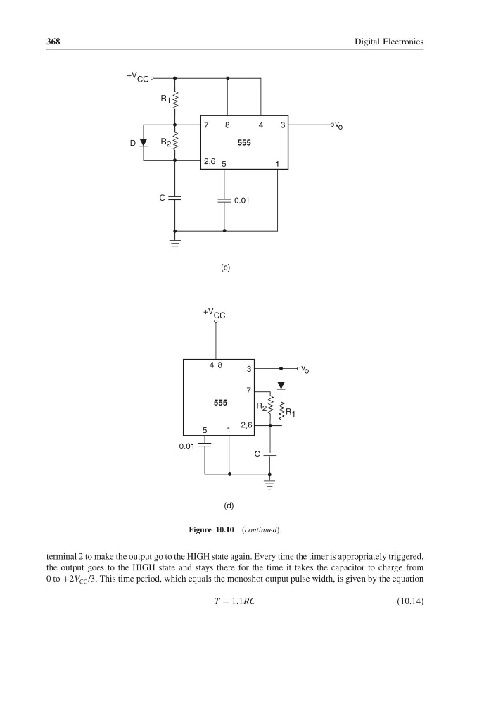
Figure 10.10 (continued).
terminal 2 to make the output go to the HIGH state again. Every time the timer is appropriately triggered,
the output goes to the HIGH state and stays there for the time it takes the capacitor to charge from
0 to +2V CC /3. This time period, which equals the monoshot output pulse width, is given by the equation
T = 11RC
(10.14)
Digital Electronics
R 1
(c)
R 2
2,6
7
8
4
3
5
1
0.01
C
+V CC
555
v o
R 1
(d)
R 2
2,6
7
8
4
3
5
1
0.01
C
+V CC
555
v o
D
Figure 10.10 (continued).
terminal 2 to make the output go to the HIGH state again. Every time the timer is appropriately triggered,
the output goes to the HIGH state and stays there for the time it takes the capacitor to charge from
0 to +2V CC /3. This time period, which equals the monoshot output pulse width, is given by the equation
T = 11RC
(10.14)