

Flip-Flops and Related Devices
367
R 1
t ON
t OFF
t
— V CC
1
3
— V CC
2
3
v C
v o
t
(a)
(b)
R 2
2,6
7
8
4
3
5
1
0.01
C
+V CC
555
o
v o
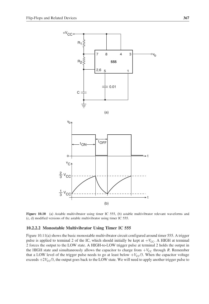
Figure 10.10 (a) Astable multivibrator using timer IC 555, (b) astable multivibrator relevant waveforms and
(c, d) modified versions of the astable multivibrator using timer IC 555.
10.2.2.2 Monostable Multivibrator Using Timer IC 555
Figure 10.11(a) shows the basic monostable multivibrator circuit configured around timer 555. A trigger
pulse is applied to terminal 2 of the IC, which should initially be kept at +V CC . A HIGH at terminal
2 forces the output to the LOW state. A HIGH-to-LOW trigger pulse at terminal 2 holds the output in
the HIGH state and simultaneously allows the capacitor to charge from +V CC through R. Remember
that a LOW level of the trigger pulse needs to go at least below +V CC /3. When the capacitor voltage
exceeds +2V CC /3, the output goes back to the LOW state. We will need to apply another trigger pulse to
367
R 1
t ON
t OFF
t
— V CC
1
3
— V CC
2
3
v C
v o
t
(a)
(b)
R 2
2,6
7
8
4
3
5
1
0.01
C
+V CC
555
o
v o
Figure 10.10 (a) Astable multivibrator using timer IC 555, (b) astable multivibrator relevant waveforms and
(c, d) modified versions of the astable multivibrator using timer IC 555.
10.2.2.2 Monostable Multivibrator Using Timer IC 555
Figure 10.11(a) shows the basic monostable multivibrator circuit configured around timer 555. A trigger
pulse is applied to terminal 2 of the IC, which should initially be kept at +V CC . A HIGH at terminal
2 forces the output to the LOW state. A HIGH-to-LOW trigger pulse at terminal 2 holds the output in
the HIGH state and simultaneously allows the capacitor to charge from +V CC through R. Remember
that a LOW level of the trigger pulse needs to go at least below +V CC /3. When the capacitor voltage
exceeds +2V CC /3, the output goes back to the LOW state. We will need to apply another trigger pulse to