

Flip-Flops and Related Devices
365
Q
GND
A 1
A 2
74123
Vcc
C EXT
Output
C
+
Q
+Vcc
R
(a)
R EXT
B 1
B 2
CLR
Q
GND
A 1
A 2
74123
Vcc
C EXT
Output
C
+
Q
+Vcc
R
(b)
B 1
B 2
CLR
/C EXT
R EXT/CEXT
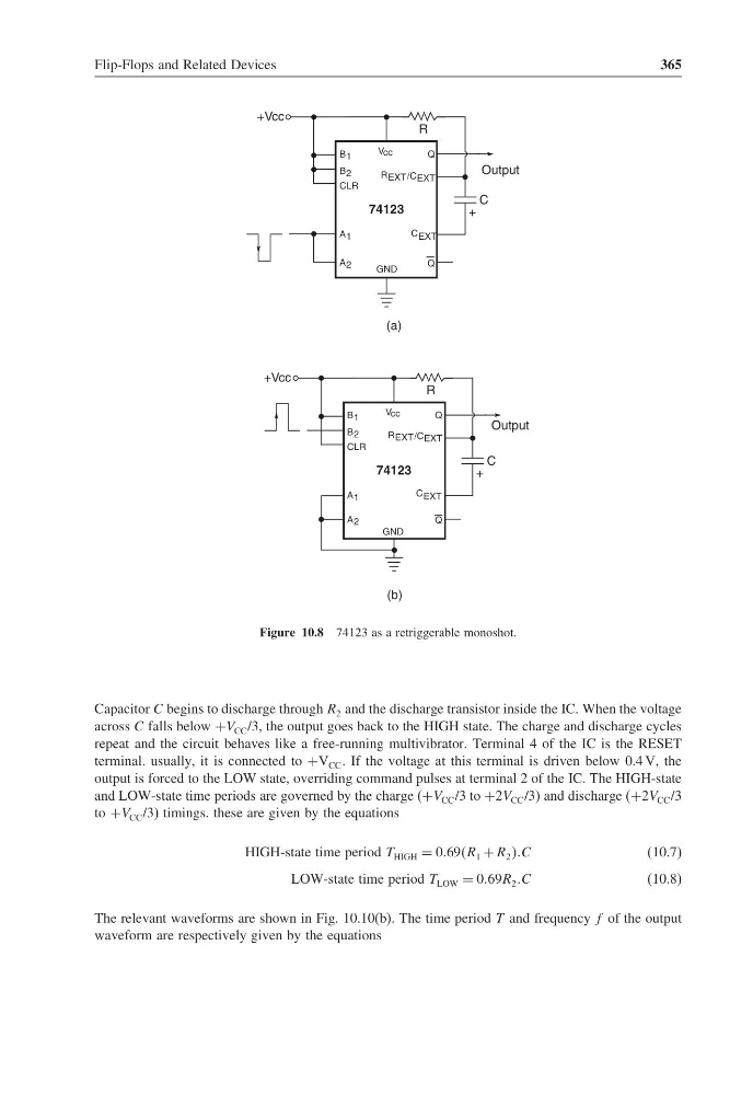
Figure 10.8 74123 as a retriggerable monoshot.
Capacitor C begins to discharge through R 2 and the discharge transistor inside the IC. When the voltage
across C falls below +V CC /3, the output goes back to the HIGH state. The charge and discharge cycles
repeat and the circuit behaves like a free-running multivibrator. Terminal 4 of the IC is the RESET
terminal. usually, it is connected to +V CC . If the voltage at this terminal is driven below 0.4 V, the
output is forced to the LOW state, overriding command pulses at terminal 2 of the IC. The HIGH-state
and LOW-state time periods are governed by the charge (+V CC /3 to +2V CC /3) and discharge (+2V CC /3
to +V CC /3) timings. these are given by the equations
HIGH-state time period T HIGH = 069R 1 + R 2 C
(10.7)
LOW-state time period T LOW = 069R 2 C
(10.8)
The relevant waveforms are shown in Fig. 10.10(b). The time period T and frequency f of the output
waveform are respectively given by the equations
365
Q
GND
A 1
A 2
74123
Vcc
C EXT
Output
C
+
Q
+Vcc
R
(a)
R EXT
B 1
B 2
CLR
Q
GND
A 1
A 2
74123
Vcc
C EXT
Output
C
+
Q
+Vcc
R
(b)
B 1
B 2
CLR
/C EXT
R EXT/CEXT
Figure 10.8 74123 as a retriggerable monoshot.
Capacitor C begins to discharge through R 2 and the discharge transistor inside the IC. When the voltage
across C falls below +V CC /3, the output goes back to the HIGH state. The charge and discharge cycles
repeat and the circuit behaves like a free-running multivibrator. Terminal 4 of the IC is the RESET
terminal. usually, it is connected to +V CC . If the voltage at this terminal is driven below 0.4 V, the
output is forced to the LOW state, overriding command pulses at terminal 2 of the IC. The HIGH-state
and LOW-state time periods are governed by the charge (+V CC /3 to +2V CC /3) and discharge (+2V CC /3
to +V CC /3) timings. these are given by the equations
HIGH-state time period T HIGH = 069R 1 + R 2 C
(10.7)
LOW-state time period T LOW = 069R 2 C
(10.8)
The relevant waveforms are shown in Fig. 10.10(b). The time period T and frequency f of the output
waveform are respectively given by the equations