

364
Digital Electronics
B
Q
GND
A 1
A 2
74121
Vcc
C EXT
Output
C
+
Q
+Vcc
R
(a)
B
Q
GND
A 1
A 2
74121
Vcc
C EXT
/C EXT
R EXT
Output
C
+
Q
+Vcc
R
(b)
/C EXT
R EXT
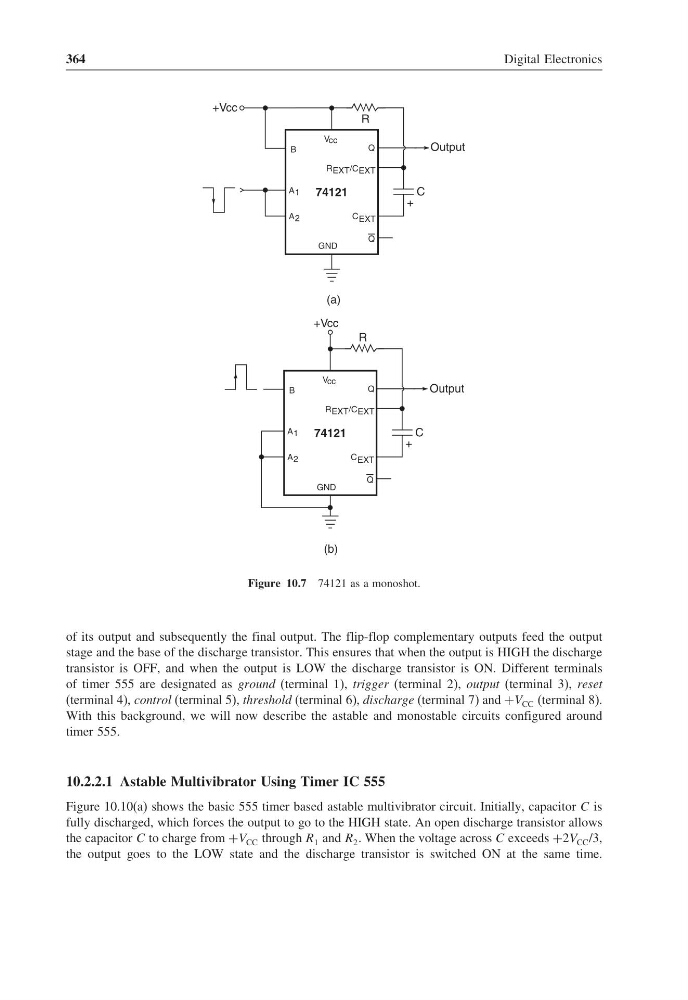
Figure 10.7 74121 as a monoshot.
of its output and subsequently the final output. The flip-flop complementary outputs feed the output
stage and the base of the discharge transistor. This ensures that when the output is HIGH the discharge
transistor is OFF, and when the output is LOW the discharge transistor is ON. Different terminals
of timer 555 are designated as ground (terminal 1), trigger (terminal 2), output (terminal 3), reset
(terminal 4), control (terminal 5), threshold (terminal 6), discharge (terminal 7) and +V CC (terminal 8).
With this background, we will now describe the astable and monostable circuits configured around
timer 555.
10.2.2.1 Astable Multivibrator Using Timer IC 555
Figure 10.10(a) shows the basic 555 timer based astable multivibrator circuit. Initially, capacitor C is
fully discharged, which forces the output to go to the HIGH state. An open discharge transistor allows
the capacitor C to charge from +V CC through R 1 and R 2 . When the voltage across C exceeds +2V CC /3,
the output goes to the LOW state and the discharge transistor is switched ON at the same time.
Digital Electronics
B
Q
GND
A 1
A 2
74121
Vcc
C EXT
Output
C
+
Q
+Vcc
R
(a)
B
Q
GND
A 1
A 2
74121
Vcc
C EXT
/C EXT
R EXT
Output
C
+
Q
+Vcc
R
(b)
/C EXT
R EXT
Figure 10.7 74121 as a monoshot.
of its output and subsequently the final output. The flip-flop complementary outputs feed the output
stage and the base of the discharge transistor. This ensures that when the output is HIGH the discharge
transistor is OFF, and when the output is LOW the discharge transistor is ON. Different terminals
of timer 555 are designated as ground (terminal 1), trigger (terminal 2), output (terminal 3), reset
(terminal 4), control (terminal 5), threshold (terminal 6), discharge (terminal 7) and +V CC (terminal 8).
With this background, we will now describe the astable and monostable circuits configured around
timer 555.
10.2.2.1 Astable Multivibrator Using Timer IC 555
Figure 10.10(a) shows the basic 555 timer based astable multivibrator circuit. Initially, capacitor C is
fully discharged, which forces the output to go to the HIGH state. An open discharge transistor allows
the capacitor C to charge from +V CC through R 1 and R 2 . When the voltage across C exceeds +2V CC /3,
the output goes to the LOW state and the discharge transistor is switched ON at the same time.