

360
Digital Electronics
V in
V UT
V LT
V CE (sat)
@
V cc
V o
0
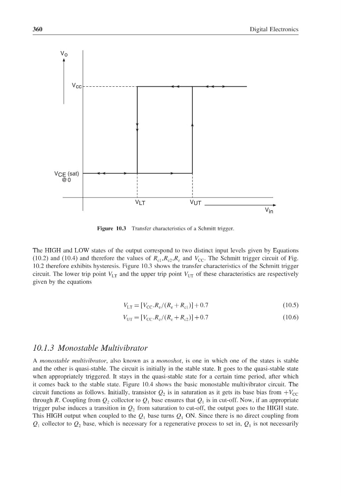
Figure 10.3 Transfer characteristics of a Schmitt trigger.
The HIGH and LOW states of the output correspond to two distinct input levels given by Equations
(10.2) and (10.4) and therefore the values of R c1 ,R c2 ,R e and V CC The Schmitt trigger circuit of Fig.
10.2 therefore exhibits hysteresis. Figure 10.3 shows the transfer characteristics of the Schmitt trigger
circuit. The lower trip point V LT and the upper trip point V UT of these characteristics are respectively
given by the equations
V LT = V CC R e //R e + R c1 + 07
(10.5)
V UT = V CC R e //R e + R c2 + 07
(10.6)
10.1.3 Monostable Multivibrator
A monostable multivibrator, also known as a monoshot, is one in which one of the states is stable
and the other is quasi-stable. The circuit is initially in the stable state. It goes to the quasi-stable state
when appropriately triggered. It stays in the quasi-stable state for a certain time period, after which
it comes back to the stable state. Figure 10.4 shows the basic monostable multivibrator circuit. The
circuit functions as follows. Initially, transistor Q 2 is in saturation as it gets its base bias from +V CC
through RR Coupling from Q 2 collector to Q 1 base ensures that Q 1 is in cut-off. Now, if an appropriate
trigger pulse induces a transition in Q 2 from saturation to cut-off, the output goes to the HIGH state.
This HIGH output when coupled to the Q 1 base turns Q 1 ON. Since there is no direct coupling from
Q 1 collector to Q 2 base, which is necessary for a regenerative process to set in, Q 1 is not necessarily
Digital Electronics
V in
V UT
V LT
V CE (sat)
@
V cc
V o
0
Figure 10.3 Transfer characteristics of a Schmitt trigger.
The HIGH and LOW states of the output correspond to two distinct input levels given by Equations
(10.2) and (10.4) and therefore the values of R c1 ,R c2 ,R e and V CC The Schmitt trigger circuit of Fig.
10.2 therefore exhibits hysteresis. Figure 10.3 shows the transfer characteristics of the Schmitt trigger
circuit. The lower trip point V LT and the upper trip point V UT of these characteristics are respectively
given by the equations
V LT = V CC R e //R e + R c1 + 07
(10.5)
V UT = V CC R e //R e + R c2 + 07
(10.6)
10.1.3 Monostable Multivibrator
A monostable multivibrator, also known as a monoshot, is one in which one of the states is stable
and the other is quasi-stable. The circuit is initially in the stable state. It goes to the quasi-stable state
when appropriately triggered. It stays in the quasi-stable state for a certain time period, after which
it comes back to the stable state. Figure 10.4 shows the basic monostable multivibrator circuit. The
circuit functions as follows. Initially, transistor Q 2 is in saturation as it gets its base bias from +V CC
through RR Coupling from Q 2 collector to Q 1 base ensures that Q 1 is in cut-off. Now, if an appropriate
trigger pulse induces a transition in Q 2 from saturation to cut-off, the output goes to the HIGH state.
This HIGH output when coupled to the Q 1 base turns Q 1 ON. Since there is no direct coupling from
Q 1 collector to Q 2 base, which is necessary for a regenerative process to set in, Q 1 is not necessarily