

Multiplexers and Demultiplexers
285
X
D 1
D 3
D 2
Y
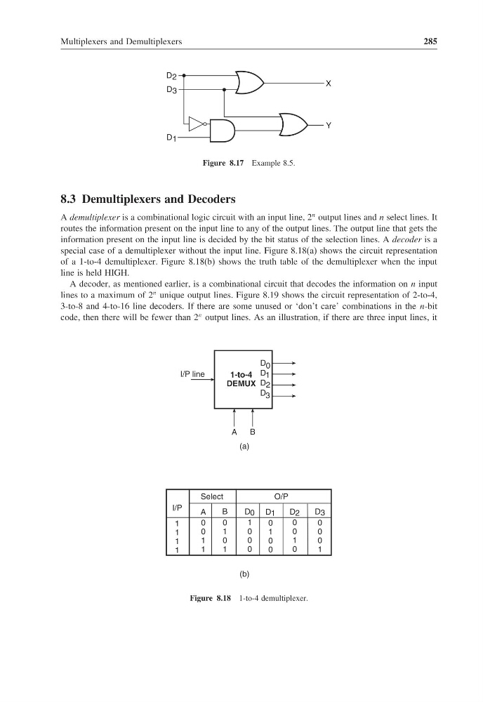
Figure 8.17 Example 8.5.
8.3 Demultiplexers and Decoders
A demultiplexer is a combinational logic circuit with an input line, 2
n output lines and n select lines. It
routes the information present on the input line to any of the output lines. The output line that gets the
information present on the input line is decided by the bit status of the selection lines. A decoder is a
special case of a demultiplexer without the input line. Figure 8.18(a) shows the circuit representation
of a 1-to-4 demultiplexer. Figure 8.18(b) shows the truth table of the demultiplexer when the input
line is held HIGH.
A decoder, as mentioned earlier, is a combinational circuit that decodes the information on n input
lines to a maximum of 2
n unique output lines. Figure 8.19 shows the circuit representation of 2-to-4,
3-to-8 and 4-to-16 line decoders. If there are some unused or ‘don’t care’ combinations in the n-bit
code, then there will be fewer than 2
n output lines. As an illustration, if there are three input lines, it
(b)
I/P
1
1
1
1
A
0
0
1
1
B
0
1
0
1
D 0
1
0
0
0
D 1
0
1
0
0
D 2
0
0
1
0
D 3
0
0
0
1
1-to-4
DEMUX
I/P line
A
B
D 0
D 1
D 2
D 3
Select
O/P
(a)
Figure 8.18 1-to-4 demultiplexer.
285
X
D 1
D 3
D 2
Y
Figure 8.17 Example 8.5.
8.3 Demultiplexers and Decoders
A demultiplexer is a combinational logic circuit with an input line, 2
n output lines and n select lines. It
routes the information present on the input line to any of the output lines. The output line that gets the
information present on the input line is decided by the bit status of the selection lines. A decoder is a
special case of a demultiplexer without the input line. Figure 8.18(a) shows the circuit representation
of a 1-to-4 demultiplexer. Figure 8.18(b) shows the truth table of the demultiplexer when the input
line is held HIGH.
A decoder, as mentioned earlier, is a combinational circuit that decodes the information on n input
lines to a maximum of 2
n unique output lines. Figure 8.19 shows the circuit representation of 2-to-4,
3-to-8 and 4-to-16 line decoders. If there are some unused or ‘don’t care’ combinations in the n-bit
code, then there will be fewer than 2
n output lines. As an illustration, if there are three input lines, it
(b)
I/P
1
1
1
1
A
0
0
1
1
B
0
1
0
1
D 0
1
0
0
0
D 1
0
1
0
0
D 2
0
0
1
0
D 3
0
0
0
1
1-to-4
DEMUX
I/P line
A
B
D 0
D 1
D 2
D 3
Select
O/P
(a)
Figure 8.18 1-to-4 demultiplexer.