

284
Digital Electronics
Example 8.4
We have an eight-line to three-line priority encoder circuit with D 0 D 1 D 2 D 3 D 4 D 5 D 6 and D 7 as
the data input lines. the output bits are A (MSB), B and C (LSB). Higher-order data bits have been
assigned a higher priority, with D 7 having the highest priority. If the data inputs and outputs are active
when LOW, determine the logic status of output bits for the following logic status of data inputs:
(a) All inputs are in logic ‘0’ state.
(b) D 1 to D 4 are in logic ‘1’ state and D 5 to D 7 are in logic ‘0’ state.
(c) D 7 is in logic ‘0’ state. The logic status of the other inputs is not known.
Solution
(a) Since all inputs are in logic ‘0’ state, it implies that all inputs are active. Since D 7 has the highest
priority and all inputs and outputs are active when LOW, the output bits are A = 0, B = 0 and
C = 0.
(b) Inputs D 5 to D 7 are the ones that are active. among these, D 7 has the highest priority. Therefore,
the output bits are A = 0, B = 0 and C = 0.
(c) D 7 is active. Since D 7 has the highest priority, it will be encoded irrespective of the logic status
of other inputs. Therefore, the output bits are A = 0, B = 0 and C = 0.
Example 8.5
Design a four-line to two-line priority encoder with active HIGH inputs and outputs, with priority
assigned to the higher-order data input line.
Solution
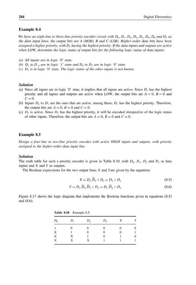
The truth table for such a priority encoder is given in Table 8.10, with D 0 , D 1 , D 2 and D 3 as data
inputs and X and Y as outputs.
The Boolean expressions for the two output lines X and Y are given by the equations
X = D 2 D 3 + D 3 = D 2 + D 3
(8.5)
Y = D 1 D 2 D 3 + D 3 = D 1 D 2 + D 3
(8.6)
Figure 8.17 shows the logic diagram that implements the Boolean functions given in equations (8.5)
and (8.6).
Table 8.10 Example 8.5.
D 0
D 1
D 2
D 3
X
Y
1
0
0
0
0
0
X
1
0
0
0
1
X
X
1
0
1
0
X
X
X
1
1
1
Digital Electronics
Example 8.4
We have an eight-line to three-line priority encoder circuit with D 0 D 1 D 2 D 3 D 4 D 5 D 6 and D 7 as
the data input lines. the output bits are A (MSB), B and C (LSB). Higher-order data bits have been
assigned a higher priority, with D 7 having the highest priority. If the data inputs and outputs are active
when LOW, determine the logic status of output bits for the following logic status of data inputs:
(a) All inputs are in logic ‘0’ state.
(b) D 1 to D 4 are in logic ‘1’ state and D 5 to D 7 are in logic ‘0’ state.
(c) D 7 is in logic ‘0’ state. The logic status of the other inputs is not known.
Solution
(a) Since all inputs are in logic ‘0’ state, it implies that all inputs are active. Since D 7 has the highest
priority and all inputs and outputs are active when LOW, the output bits are A = 0, B = 0 and
C = 0.
(b) Inputs D 5 to D 7 are the ones that are active. among these, D 7 has the highest priority. Therefore,
the output bits are A = 0, B = 0 and C = 0.
(c) D 7 is active. Since D 7 has the highest priority, it will be encoded irrespective of the logic status
of other inputs. Therefore, the output bits are A = 0, B = 0 and C = 0.
Example 8.5
Design a four-line to two-line priority encoder with active HIGH inputs and outputs, with priority
assigned to the higher-order data input line.
Solution
The truth table for such a priority encoder is given in Table 8.10, with D 0 , D 1 , D 2 and D 3 as data
inputs and X and Y as outputs.
The Boolean expressions for the two output lines X and Y are given by the equations
X = D 2 D 3 + D 3 = D 2 + D 3
(8.5)
Y = D 1 D 2 D 3 + D 3 = D 1 D 2 + D 3
(8.6)
Figure 8.17 shows the logic diagram that implements the Boolean functions given in equations (8.5)
and (8.6).
Table 8.10 Example 8.5.
D 0
D 1
D 2
D 3
X
Y
1
0
0
0
0
0
X
1
0
0
0
1
X
X
1
0
1
0
X
X
X
1
1
1