

286
Digital Electronics
0
1
2
3
2-to-4
A
B
0
1
7
3-to-8
A
B
C
0
1
15
4-to-16
A
B
C
D
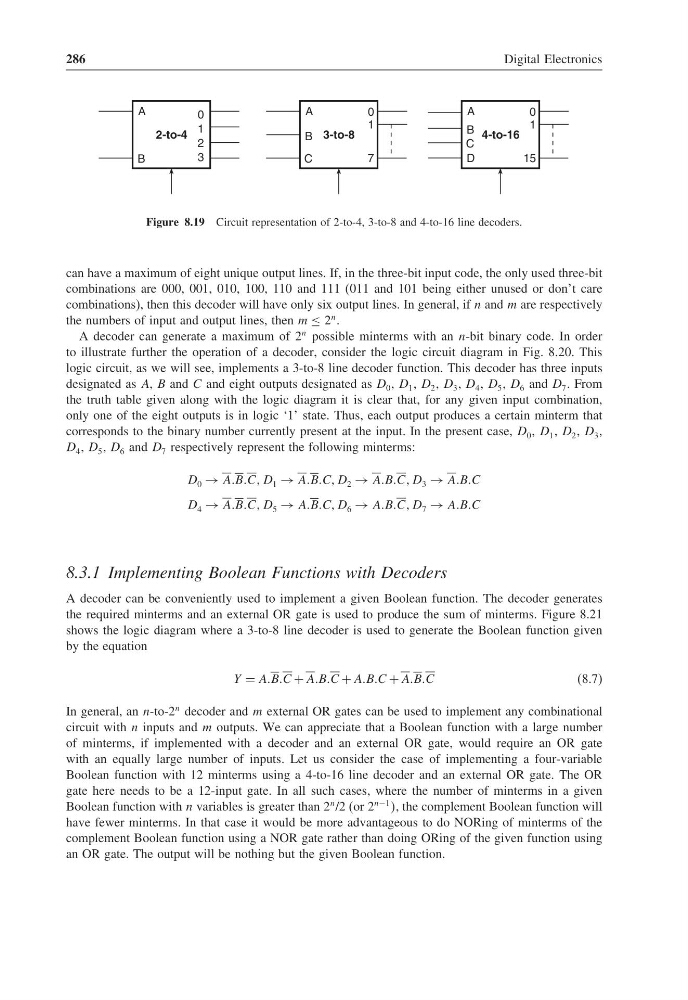
Figure 8.19 Circuit representation of 2-to-4, 3-to-8 and 4-to-16 line decoders.
can have a maximum of eight unique output lines. If, in the three-bit input code, the only used three-bit
combinations are 000, 001, 010, 100, 110 and 111 (011 and 101 being either unused or don’t care
combinations), then this decoder will have only six output lines. In general, if n and m are respectively
the numbers of input and output lines, then m ≤ 2
n .
A decoder can generate a maximum of 2
n possible minterms with an n-bit binary code. In order
to illustrate further the operation of a decoder, consider the logic circuit diagram in Fig. 8.20. This
logic circuit, as we will see, implements a 3-to-8 line decoder function. This decoder has three inputs
designated as A, B and C and eight outputs designated as D 0 , D 1 , D 2 , D 3 , D 4 , D 5 , D 6 and D 7 . From
the truth table given along with the logic diagram it is clear that, for any given input combination,
only one of the eight outputs is in logic ‘1’ state. Thus, each output produces a certain minterm that
corresponds to the binary number currently present at the input. In the present case, D 0 , D 1 , D 2 , D 3 ,
D 4 , D 5 , D 6 and D 7 respectively represent the following minterms:
D 0 → AABBCC D 1 → AABBCC D 2 → AABBCC D 3 → AABBC
D 4 → AABBCC D 5 → AABBCC D 6 → AABBCC D 7 → AABBC
8.3.1 Implementing Boolean Functions with Decoders
A decoder can be conveniently used to implement a given Boolean function. The decoder generates
the required minterms and an external OR gate is used to produce the sum of minterms. Figure 8.21
shows the logic diagram where a 3-to-8 line decoder is used to generate the Boolean function given
by the equation
Y = AABBC + AABBC + AABBC + AABBC
(8.7)
In general, an n-to-2
n decoder and m external OR gates can be used to implement any combinational
circuit with n inputs and m outputs. We can appreciate that a Boolean function with a large number
of minterms, if implemented with a decoder and an external OR gate, would require an OR gate
with an equally large number of inputs. Let us consider the case of implementing a four-variable
Boolean function with 12 minterms using a 4-to-16 line decoder and an external OR gate. The OR
gate here needs to be a 12-input gate. In all such cases, where the number of minterms in a given
Boolean function with n variables is greater than 2
n /2 (or 2
n−1 , the complement Boolean function will
have fewer minterms. In that case it would be more advantageous to do NORing of minterms of the
complement Boolean function using a NOR gate rather than doing ORing of the given function using
an OR gate. The output will be nothing but the given Boolean function.
Digital Electronics
0
1
2
3
2-to-4
A
B
0
1
7
3-to-8
A
B
C
0
1
15
4-to-16
A
B
C
D
Figure 8.19 Circuit representation of 2-to-4, 3-to-8 and 4-to-16 line decoders.
can have a maximum of eight unique output lines. If, in the three-bit input code, the only used three-bit
combinations are 000, 001, 010, 100, 110 and 111 (011 and 101 being either unused or don’t care
combinations), then this decoder will have only six output lines. In general, if n and m are respectively
the numbers of input and output lines, then m ≤ 2
n .
A decoder can generate a maximum of 2
n possible minterms with an n-bit binary code. In order
to illustrate further the operation of a decoder, consider the logic circuit diagram in Fig. 8.20. This
logic circuit, as we will see, implements a 3-to-8 line decoder function. This decoder has three inputs
designated as A, B and C and eight outputs designated as D 0 , D 1 , D 2 , D 3 , D 4 , D 5 , D 6 and D 7 . From
the truth table given along with the logic diagram it is clear that, for any given input combination,
only one of the eight outputs is in logic ‘1’ state. Thus, each output produces a certain minterm that
corresponds to the binary number currently present at the input. In the present case, D 0 , D 1 , D 2 , D 3 ,
D 4 , D 5 , D 6 and D 7 respectively represent the following minterms:
D 0 → AABBCC D 1 → AABBCC D 2 → AABBCC D 3 → AABBC
D 4 → AABBCC D 5 → AABBCC D 6 → AABBCC D 7 → AABBC
8.3.1 Implementing Boolean Functions with Decoders
A decoder can be conveniently used to implement a given Boolean function. The decoder generates
the required minterms and an external OR gate is used to produce the sum of minterms. Figure 8.21
shows the logic diagram where a 3-to-8 line decoder is used to generate the Boolean function given
by the equation
Y = AABBC + AABBC + AABBC + AABBC
(8.7)
In general, an n-to-2
n decoder and m external OR gates can be used to implement any combinational
circuit with n inputs and m outputs. We can appreciate that a Boolean function with a large number
of minterms, if implemented with a decoder and an external OR gate, would require an OR gate
with an equally large number of inputs. Let us consider the case of implementing a four-variable
Boolean function with 12 minterms using a 4-to-16 line decoder and an external OR gate. The OR
gate here needs to be a 12-input gate. In all such cases, where the number of minterms in a given
Boolean function with n variables is greater than 2
n /2 (or 2
n−1 , the complement Boolean function will
have fewer minterms. In that case it would be more advantageous to do NORing of minterms of the
complement Boolean function using a NOR gate rather than doing ORing of the given function using
an OR gate. The output will be nothing but the given Boolean function.