

276
Digital Electronics
Table 8.2 Implementation table for
multiplexers.
I 0
I 1
I 2
I 3
A
0
1
2
3
A
4
5
6
7
A
0
A
A
Table 8.3 Implementation table for multiplexers.
I 0
I 1
I 2
I 3
C
0
2
4
6
C
1
3
5
7
0
C
C
C
It is not necessary to choose only the leftmost variable in the sequence to be used as input to
the multiplexer. Any of the variables can be used provided the implementation table is constructed
accordingly. In the problem illustrated above, A was chosen as the variable for the input lines,
and accordingly the first row of the implementation table contained those entries where ‘A’ was
complemented and the second row contained those entries where A was uncomplemented. If we
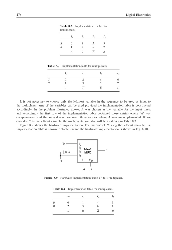
consider C as the left-out variable, the implementation table will be as shown in Table 8.3.
Figure 8.9 shows the hardware implementation. For the case of B being the left-out variable, the
implementation table is shown in Table 8.4 and the hardware implementation is shown in Fig. 8.10.
4-to-1
MUX
F
A
B
I 0
I 1
I 2
I 3
S 1 S 0
C
'0’
Figure 8.9 Hardware implementation using a 4-to-1 multiplexer.
Table 8.4 Implementation table for multiplexers.
I 0
I 1
I 2
I 3
B
0
1
4
5
B
2
3
6
7
B
0
B
B
Digital Electronics
Table 8.2 Implementation table for
multiplexers.
I 0
I 1
I 2
I 3
A
0
1
2
3
A
4
5
6
7
A
0
A
A
Table 8.3 Implementation table for multiplexers.
I 0
I 1
I 2
I 3
C
0
2
4
6
C
1
3
5
7
0
C
C
C
It is not necessary to choose only the leftmost variable in the sequence to be used as input to
the multiplexer. Any of the variables can be used provided the implementation table is constructed
accordingly. In the problem illustrated above, A was chosen as the variable for the input lines,
and accordingly the first row of the implementation table contained those entries where ‘A’ was
complemented and the second row contained those entries where A was uncomplemented. If we
consider C as the left-out variable, the implementation table will be as shown in Table 8.3.
Figure 8.9 shows the hardware implementation. For the case of B being the left-out variable, the
implementation table is shown in Table 8.4 and the hardware implementation is shown in Fig. 8.10.
4-to-1
MUX
F
A
B
I 0
I 1
I 2
I 3
S 1 S 0
C
'0’
Figure 8.9 Hardware implementation using a 4-to-1 multiplexer.
Table 8.4 Implementation table for multiplexers.
I 0
I 1
I 2
I 3
B
0
1
4
5
B
2
3
6
7
B
0
B
B