

Multiplexers and Demultiplexers
275
(b)
4-to-1
MUX
F
C
I 0
I 1
I 2
I 3
S 1 S 0
A
B
8-to-1
MUX
F
I 0
I 1
I 2
I 3
I 4
I 5
I 6
I 7
A B C
'1'
(a)
'0’
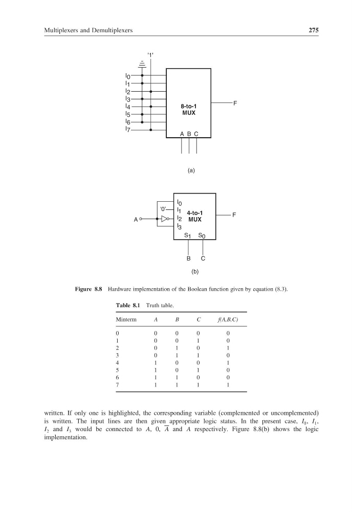
Figure 8.8 Hardware implementation of the Boolean function given by equation (8.3).
Table 8.1 Truth table.
Minterm
A
B
C
f(A,B,C)
0
0
0
0
0
1
0
0
1
0
2
0
1
0
1
3
0
1
1
0
4
1
0
0
1
5
1
0
1
0
6
1
1
0
0
7
1
1
1
1
written. If only one is highlighted, the corresponding variable (complemented or uncomplemented)
is written. The input lines are then given appropriate logic status. In the present case, I 0 , I 1 ,
I 2 and I 3 would be connected to A, 0, A and A respectively. Figure 8.8(b) shows the logic
implementation.
275
(b)
4-to-1
MUX
F
C
I 0
I 1
I 2
I 3
S 1 S 0
A
B
8-to-1
MUX
F
I 0
I 1
I 2
I 3
I 4
I 5
I 6
I 7
A B C
'1'
(a)
'0’
Figure 8.8 Hardware implementation of the Boolean function given by equation (8.3).
Table 8.1 Truth table.
Minterm
A
B
C
f(A,B,C)
0
0
0
0
0
1
0
0
1
0
2
0
1
0
1
3
0
1
1
0
4
1
0
0
1
5
1
0
1
0
6
1
1
0
0
7
1
1
1
1
written. If only one is highlighted, the corresponding variable (complemented or uncomplemented)
is written. The input lines are then given appropriate logic status. In the present case, I 0 , I 1 ,
I 2 and I 3 would be connected to A, 0, A and A respectively. Figure 8.8(b) shows the logic
implementation.