

274
Digital Electronics
Y
I 0
I 1
I 2
I 3
S 1
S 0
EN
X
0
0
1
1
S 1
X
0
1
0
1
1
0
0
0
0
0
S 0
EN
I 0
I 1
I 2
I 3
Y
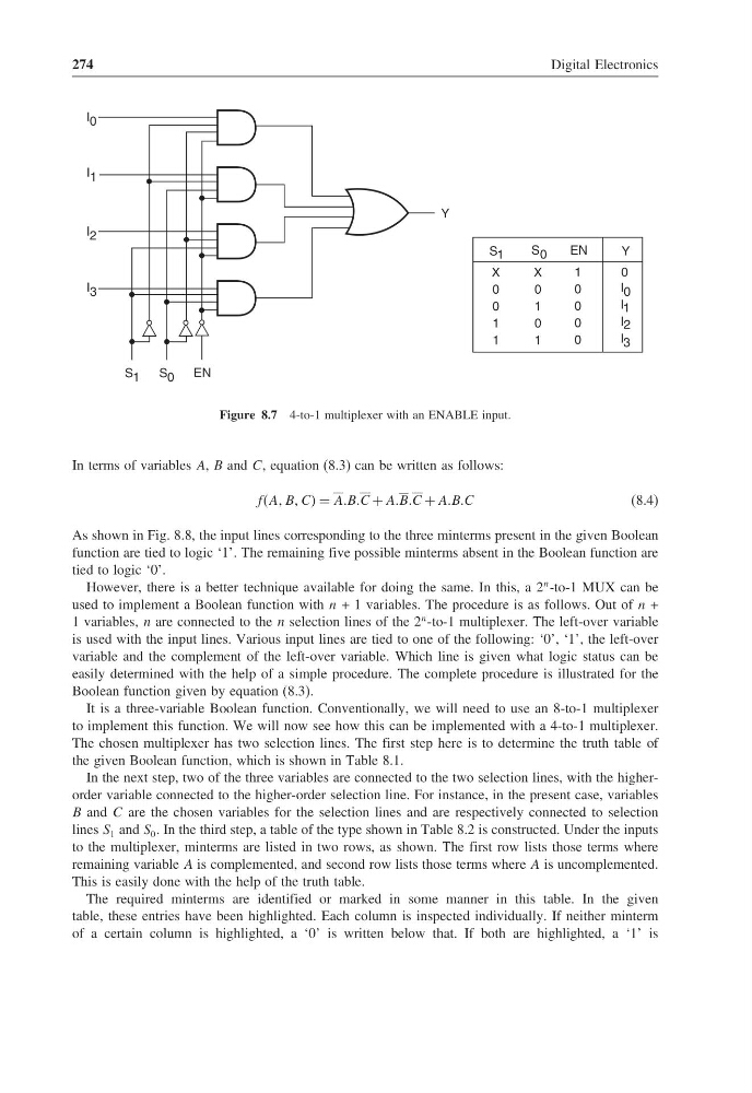
Figure 8.7 4-to-1 multiplexer with an ENABLE input.
In terms of variables A, B and C, equation (8.3) can be written as follows:
ffAA BB CC = AABBC + AABBC + AABBC
(8.4)
As shown in Fig. 8.8, the input lines corresponding to the three minterms present in the given Boolean
function are tied to logic ‘1’. The remaining five possible minterms absent in the Boolean function are
tied to logic ‘0’.
However, there is a better technique available for doing the same. In this, a 2
n -to-1 MUX can be
used to implement a Boolean function with n + 1 variables. The procedure is as follows. Out of n +
1 variables, n are connected to the n selection lines of the 2
n -to-1 multiplexer. The left-over variable
is used with the input lines. Various input lines are tied to one of the following: ‘0’, ‘1’, the left-over
variable and the complement of the left-over variable. Which line is given what logic status can be
easily determined with the help of a simple procedure. The complete procedure is illustrated for the
Boolean function given by equation (8.3).
It is a three-variable Boolean function. Conventionally, we will need to use an 8-to-1 multiplexer
to implement this function. We will now see how this can be implemented with a 4-to-1 multiplexer.
The chosen multiplexer has two selection lines. The first step here is to determine the truth table of
the given Boolean function, which is shown in Table 8.1.
In the next step, two of the three variables are connected to the two selection lines, with the higherorder variable connected to the higher-order selection line. For instance, in the present case, variables
B and C are the chosen variables for the selection lines and are respectively connected to selection
lines S 1 and S 0 . In the third step, a table of the type shown in Table 8.2 is constructed. Under the inputs
to the multiplexer, minterms are listed in two rows, as shown. The first row lists those terms where
remaining variable A is complemented, and second row lists those terms where A is uncomplemented.
This is easily done with the help of the truth table.
The required minterms are identified or marked in some manner in this table. In the given
table, these entries have been highlighted. Each column is inspected individually. If neither minterm
of a certain column is highlighted, a ‘0’ is written below that. If both are highlighted, a ‘1’ is
Digital Electronics
Y
I 0
I 1
I 2
I 3
S 1
S 0
EN
X
0
0
1
1
S 1
X
0
1
0
1
1
0
0
0
0
0
S 0
EN
I 0
I 1
I 2
I 3
Y
Figure 8.7 4-to-1 multiplexer with an ENABLE input.
In terms of variables A, B and C, equation (8.3) can be written as follows:
ffAA BB CC = AABBC + AABBC + AABBC
(8.4)
As shown in Fig. 8.8, the input lines corresponding to the three minterms present in the given Boolean
function are tied to logic ‘1’. The remaining five possible minterms absent in the Boolean function are
tied to logic ‘0’.
However, there is a better technique available for doing the same. In this, a 2
n -to-1 MUX can be
used to implement a Boolean function with n + 1 variables. The procedure is as follows. Out of n +
1 variables, n are connected to the n selection lines of the 2
n -to-1 multiplexer. The left-over variable
is used with the input lines. Various input lines are tied to one of the following: ‘0’, ‘1’, the left-over
variable and the complement of the left-over variable. Which line is given what logic status can be
easily determined with the help of a simple procedure. The complete procedure is illustrated for the
Boolean function given by equation (8.3).
It is a three-variable Boolean function. Conventionally, we will need to use an 8-to-1 multiplexer
to implement this function. We will now see how this can be implemented with a 4-to-1 multiplexer.
The chosen multiplexer has two selection lines. The first step here is to determine the truth table of
the given Boolean function, which is shown in Table 8.1.
In the next step, two of the three variables are connected to the two selection lines, with the higherorder variable connected to the higher-order selection line. For instance, in the present case, variables
B and C are the chosen variables for the selection lines and are respectively connected to selection
lines S 1 and S 0 . In the third step, a table of the type shown in Table 8.2 is constructed. Under the inputs
to the multiplexer, minterms are listed in two rows, as shown. The first row lists those terms where
remaining variable A is complemented, and second row lists those terms where A is uncomplemented.
This is easily done with the help of the truth table.
The required minterms are identified or marked in some manner in this table. In the given
table, these entries have been highlighted. Each column is inspected individually. If neither minterm
of a certain column is highlighted, a ‘0’ is written below that. If both are highlighted, a ‘1’ is