

Multiplexers and Demultiplexers
273
Y
I 0
I 1
I 2
I 3
S 1
S 0
0
0
1
1
S 1
0
1
0
1
S 0
I 0
I 1
I 2
I 3
Y
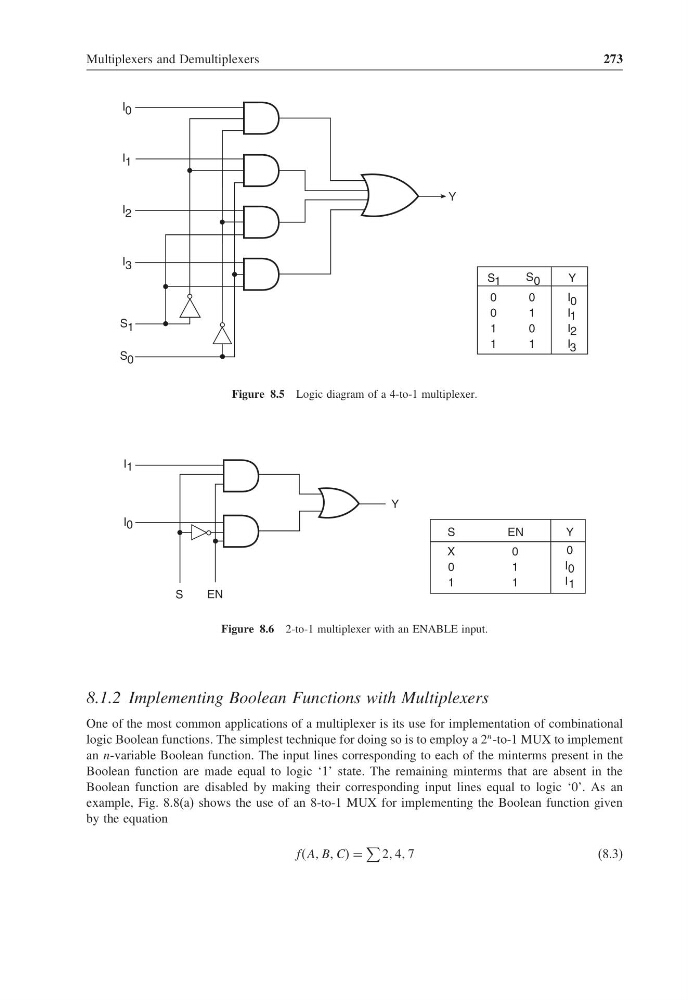
Figure 8.5 Logic diagram of a 4-to-1 multiplexer.
I 1
Y
I 0
S
EN
X
0
1
S
0
1
1
EN
0
I 0
I 1
Y
Figure 8.6 2-to-1 multiplexer with an ENABLE input.
8.1.2 Implementing Boolean Functions with Multiplexers
One of the most common applications of a multiplexer is its use for implementation of combinational
logic Boolean functions. The simplest technique for doing so is to employ a 2
n -to-1 MUX to implement
an n-variable Boolean function. The input lines corresponding to each of the minterms present in the
Boolean function are made equal to logic ‘1’ state. The remaining minterms that are absent in the
Boolean function are disabled by making their corresponding input lines equal to logic ‘0’. As an
example, Fig. 8.8(a) shows the use of an 8-to-1 MUX for implementing the Boolean function given
by the equation
ffAA BB CC =
2 4 7
(8.3)
273
Y
I 0
I 1
I 2
I 3
S 1
S 0
0
0
1
1
S 1
0
1
0
1
S 0
I 0
I 1
I 2
I 3
Y
Figure 8.5 Logic diagram of a 4-to-1 multiplexer.
I 1
Y
I 0
S
EN
X
0
1
S
0
1
1
EN
0
I 0
I 1
Y
Figure 8.6 2-to-1 multiplexer with an ENABLE input.
8.1.2 Implementing Boolean Functions with Multiplexers
One of the most common applications of a multiplexer is its use for implementation of combinational
logic Boolean functions. The simplest technique for doing so is to employ a 2
n -to-1 MUX to implement
an n-variable Boolean function. The input lines corresponding to each of the minterms present in the
Boolean function are made equal to logic ‘1’ state. The remaining minterms that are absent in the
Boolean function are disabled by making their corresponding input lines equal to logic ‘0’. As an
example, Fig. 8.8(a) shows the use of an 8-to-1 MUX for implementing the Boolean function given
by the equation
ffAA BB CC =
2 4 7
(8.3)