

272
Digital Electronics
2-to-1
MUX
Y
S
I 0
I 1
(a)
0
1
S
I 0
I 1
Y
(b)
I 1
Y
I 0
S
(c)
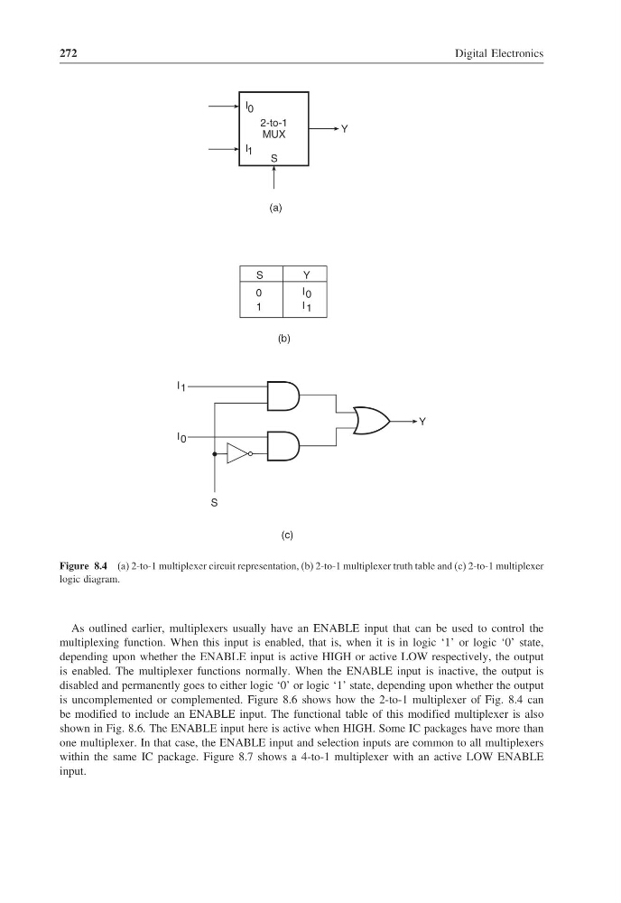
Figure 8.4 (a) 2-to-1 multiplexer circuit representation, (b) 2-to-1 multiplexer truth table and (c) 2-to-1 multiplexer
logic diagram.
As outlined earlier, multiplexers usually have an ENABLE input that can be used to control the
multiplexing function. When this input is enabled, that is, when it is in logic ‘1’ or logic ‘0’ state,
depending upon whether the ENABLE input is active HIGH or active LOW respectively, the output
is enabled. The multiplexer functions normally. When the ENABLE input is inactive, the output is
disabled and permanently goes to either logic ‘0’ or logic ‘1’ state, depending upon whether the output
is uncomplemented or complemented. Figure 8.6 shows how the 2-to-1 multiplexer of Fig. 8.4 can
be modified to include an ENABLE input. The functional table of this modified multiplexer is also
shown in Fig. 8.6. The ENABLE input here is active when HIGH. Some IC packages have more than
one multiplexer. In that case, the ENABLE input and selection inputs are common to all multiplexers
within the same IC package. Figure 8.7 shows a 4-to-1 multiplexer with an active LOW ENABLE
input.
Digital Electronics
2-to-1
MUX
Y
S
I 0
I 1
(a)
0
1
S
I 0
I 1
Y
(b)
I 1
Y
I 0
S
(c)
Figure 8.4 (a) 2-to-1 multiplexer circuit representation, (b) 2-to-1 multiplexer truth table and (c) 2-to-1 multiplexer
logic diagram.
As outlined earlier, multiplexers usually have an ENABLE input that can be used to control the
multiplexing function. When this input is enabled, that is, when it is in logic ‘1’ or logic ‘0’ state,
depending upon whether the ENABLE input is active HIGH or active LOW respectively, the output
is enabled. The multiplexer functions normally. When the ENABLE input is inactive, the output is
disabled and permanently goes to either logic ‘0’ or logic ‘1’ state, depending upon whether the output
is uncomplemented or complemented. Figure 8.6 shows how the 2-to-1 multiplexer of Fig. 8.4 can
be modified to include an ENABLE input. The functional table of this modified multiplexer is also
shown in Fig. 8.6. The ENABLE input here is active when HIGH. Some IC packages have more than
one multiplexer. In that case, the ENABLE input and selection inputs are common to all multiplexers
within the same IC package. Figure 8.7 shows a 4-to-1 multiplexer with an active LOW ENABLE
input.