

Multiplexers and Demultiplexers
277
B
F
I 0
I 1
I 2
I 3
S 1 S 0
A
C
4-to-1
MUX
'0’
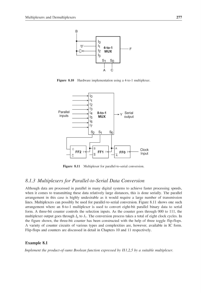
Figure 8.10 Hardware implementation using a 4-to-1 multiplexer.
Figure 8.11 Multiplexer for parallel-to-serial conversion.
8.1.3 Multiplexers for Parallel-to-Serial Data Conversion
Although data are processed in parallel in many digital systems to achieve faster processing speeds,
when it comes to transmitting these data relatively large distances, this is done serially. The parallel
arrangement in this case is highly undesirable as it would require a large number of transmission
lines. Multiplexers can possibly be used for parallel-to-serial conversion. Figure 8.11 shows one such
arrangement where an 8-to-1 multiplexer is used to convert eight-bit parallel binary data to serial
form. A three-bit counter controls the selection inputs. As the counter goes through 000 to 111, the
multiplexer output goes through I 0 to I 7 . The conversion process takes a total of eight clock cycles. In
the figure shown, the three-bit counter has been constructed with the help of three toggle flip-flops.
A variety of counter circuits of various types and complexities are, however, available in IC form.
Flip-flops and counters are discussed in detail in Chapters 10 and 11 respectively.
Example 8.1
Implement the product-of-sums Boolean function expressed by 1,2,5 by a suitable multiplexer.
277
B
F
I 0
I 1
I 2
I 3
S 1 S 0
A
C
4-to-1
MUX
'0’
Figure 8.10 Hardware implementation using a 4-to-1 multiplexer.
Figure 8.11 Multiplexer for parallel-to-serial conversion.
8.1.3 Multiplexers for Parallel-to-Serial Data Conversion
Although data are processed in parallel in many digital systems to achieve faster processing speeds,
when it comes to transmitting these data relatively large distances, this is done serially. The parallel
arrangement in this case is highly undesirable as it would require a large number of transmission
lines. Multiplexers can possibly be used for parallel-to-serial conversion. Figure 8.11 shows one such
arrangement where an 8-to-1 multiplexer is used to convert eight-bit parallel binary data to serial
form. A three-bit counter controls the selection inputs. As the counter goes through 000 to 111, the
multiplexer output goes through I 0 to I 7 . The conversion process takes a total of eight clock cycles. In
the figure shown, the three-bit counter has been constructed with the help of three toggle flip-flops.
A variety of counter circuits of various types and complexities are, however, available in IC form.
Flip-flops and counters are discussed in detail in Chapters 10 and 11 respectively.
Example 8.1
Implement the product-of-sums Boolean function expressed by 1,2,5 by a suitable multiplexer.