

Arithmetic Circuits
255
B 4
C 4
FA
(4)
A 4
S 4
B 3
C 3
FA
(3)
A 3
S 3
B 2
C 2
FA
(2)
A 2
S 2
B 1
C 1
FA
(1)
A 1
S 1
C 5
(a)
A i
B i
C i
(b)
C i+1
S i
P i
G i
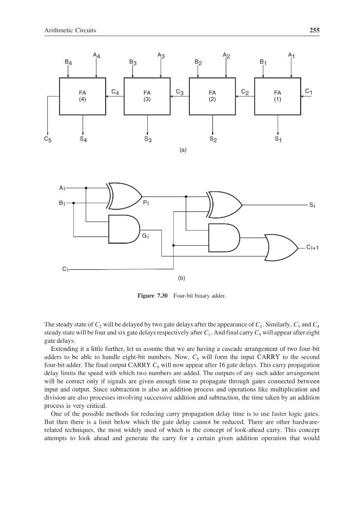
Figure 7.30 Four-bit binary adder.
The steady state of C 2 will be delayed by two gate delays after the appearance of C 1 . Similarly, C 3 and C 4
steady state will be four and six gate delays respectively after C 1 . And final carry C 5 will appear after eight
gate delays.
Extending it a little further, let us assume that we are having a cascade arrangement of two four-bit
adders to be able to handle eight-bit numbers. Now, C 5 will form the input CARRY to the second
four-bit adder. The final output CARRY C 9 will now appear after 16 gate delays. This carry propagation
delay limits the speed with which two numbers are added. The outputs of any such adder arrangement
will be correct only if signals are given enough time to propagate through gates connected between
input and output. Since subtraction is also an addition process and operations like multiplication and
division are also processes involving successive addition and subtraction, the time taken by an addition
process is very critical.
One of the possible methods for reducing carry propagation delay time is to use faster logic gates.
But then there is a limit below which the gate delay cannot be reduced. There are other hardwarerelated techniques, the most widely used of which is the concept of look-ahead carry. This concept
attempts to look ahead and generate the carry for a certain given addition operation that would
255
B 4
C 4
FA
(4)
A 4
S 4
B 3
C 3
FA
(3)
A 3
S 3
B 2
C 2
FA
(2)
A 2
S 2
B 1
C 1
FA
(1)
A 1
S 1
C 5
(a)
A i
B i
C i
(b)
C i+1
S i
P i
G i
Figure 7.30 Four-bit binary adder.
The steady state of C 2 will be delayed by two gate delays after the appearance of C 1 . Similarly, C 3 and C 4
steady state will be four and six gate delays respectively after C 1 . And final carry C 5 will appear after eight
gate delays.
Extending it a little further, let us assume that we are having a cascade arrangement of two four-bit
adders to be able to handle eight-bit numbers. Now, C 5 will form the input CARRY to the second
four-bit adder. The final output CARRY C 9 will now appear after 16 gate delays. This carry propagation
delay limits the speed with which two numbers are added. The outputs of any such adder arrangement
will be correct only if signals are given enough time to propagate through gates connected between
input and output. Since subtraction is also an addition process and operations like multiplication and
division are also processes involving successive addition and subtraction, the time taken by an addition
process is very critical.
One of the possible methods for reducing carry propagation delay time is to use faster logic gates.
But then there is a limit below which the gate delay cannot be reduced. There are other hardwarerelated techniques, the most widely used of which is the concept of look-ahead carry. This concept
attempts to look ahead and generate the carry for a certain given addition operation that would