

Arithmetic Circuits
253
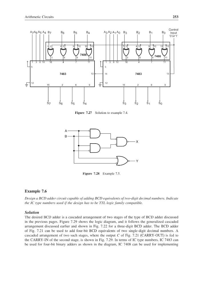
Figure 7.27 Solution to example 7.4.
A
B
X
Y
Figure 7.28 Example 7.5.
Example 7.6
Design a BCD adder circuit capable of adding BCD equivalents of two-digit decimal numbers. Indicate
the IC type numbers used if the design has to be TTL logic family compatible.
Solution
The desired BCD adder is a cascaded arrangement of two stages of the type of BCD adder discussed
in the previous pages. Figure 7.29 shows the logic diagram, and it follows the generalized cascaded
arrangement discussed earlier and shown in Fig. 7.22 for a three-digit BCD adder. The BCD adder
of Fig. 7.21 can be used to add four-bit BCD equivalents of two single-digit decimal numbers. A
cascaded arrangement of two such stages, where the output C of Fig. 7.21 (CARRY-OUT) is fed to
the CARRY-IN of the second stage, is shown in Fig. 7.29. In terms of IC type numbers, IC 7483 can
be used for four-bit binary adders as shown in the diagram, IC 7408 can be used for implementing
253
Figure 7.27 Solution to example 7.4.
A
B
X
Y
Figure 7.28 Example 7.5.
Example 7.6
Design a BCD adder circuit capable of adding BCD equivalents of two-digit decimal numbers. Indicate
the IC type numbers used if the design has to be TTL logic family compatible.
Solution
The desired BCD adder is a cascaded arrangement of two stages of the type of BCD adder discussed
in the previous pages. Figure 7.29 shows the logic diagram, and it follows the generalized cascaded
arrangement discussed earlier and shown in Fig. 7.22 for a three-digit BCD adder. The BCD adder
of Fig. 7.21 can be used to add four-bit BCD equivalents of two single-digit decimal numbers. A
cascaded arrangement of two such stages, where the output C of Fig. 7.21 (CARRY-OUT) is fed to
the CARRY-IN of the second stage, is shown in Fig. 7.29. In terms of IC type numbers, IC 7483 can
be used for four-bit binary adders as shown in the diagram, IC 7408 can be used for implementing