

252
Digital Electronics
Solution
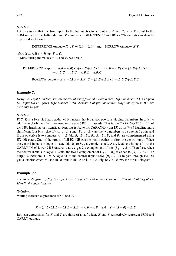
Let us assume that the two inputs to the half-subtractor circuit are X and Y , with X equal to the
SUM output of the half-adder and Y equal to C. DIFFERENCE and BORROW outputs can then be
expressed as follows:
DIFFERENCE output = X ⊕ Y = XXY + XXY and BORROW output = XXY
Also, X = AAB + AAB and Y = CC
Substituting the values of X and Y , we obtain
DIFFERENCE output = AAB + AABBBC + AAB + AABBBC = AAB + AABBBC + AAB + AABBBC
= AABBC + AABBC + AABBC + AABBC
BORROW output = XXY = AAB + AABBBC = AAB + AABBBC = AABBC + AABBC
Example 7.4
Design an eight-bit adder–subtractor circuit using four-bit binary adders, type number 7483, and quad
two-input EX-OR gates, type number 7486. Assume that pin connection diagrams of these ICs are
available to you.
Solution
IC 7483 is a four-bit binary adder, which means that it can add two four-bit binary numbers. In order to
add two eight-bit numbers, we need to use two 7483s in cascade. That is, the CARRY-OUT (pin 14) of
the 7483 handling less significant four bits is fed to the CARRY-IN (pin 13) of the 7483 handling more
significant four bits. Also, if (A 0 A 7 and (B 0 B 7 are the two numbers to be operated upon, and
if the objective is to compute A − B, bits B 0 , B 1 , B 2 , B 3 , B 4 , B 5 , B 6 and B 7 are complemented using
EX-OR gates. One of the inputs of all EX-OR gates is tied together to form the control input. When
the control input is in logic ‘1’ state, bits B 0 to B 7 get complemented. Also, feeding this logic ‘1’ to the
CARRY-IN of lower 7483 ensures that we get 2’s complement of bits (B 0 B 7 . Therefore, when
the control input is in logic ‘1’ state, the two’s complement of (B 0 B 7 is added to (A 0 A 7 . The
output is therefore A − B. A logic ‘0’ at the control input allows (B 0 B 7 to pass through EX-OR
gates uncomplemented, and the output in that case is A + B. Figure 7.27 shows the circuit diagram.
Example 7.5
The logic diagram of Fig. 7.28 performs the function of a very common arithmetic building block.
Identify the logic function.
Solution
Writing Boolean expressions for X and Y ,
X = AABBBBAABB = AAB + AABB = AAB + AAB and Y = A + BB = AAB
Boolean expressions for X and Y are those of a half-adder. X and Y respectively represent SUM and
CARRY outputs.
Digital Electronics
Solution
Let us assume that the two inputs to the half-subtractor circuit are X and Y , with X equal to the
SUM output of the half-adder and Y equal to C. DIFFERENCE and BORROW outputs can then be
expressed as follows:
DIFFERENCE output = X ⊕ Y = XXY + XXY and BORROW output = XXY
Also, X = AAB + AAB and Y = CC
Substituting the values of X and Y , we obtain
DIFFERENCE output = AAB + AABBBC + AAB + AABBBC = AAB + AABBBC + AAB + AABBBC
= AABBC + AABBC + AABBC + AABBC
BORROW output = XXY = AAB + AABBBC = AAB + AABBBC = AABBC + AABBC
Example 7.4
Design an eight-bit adder–subtractor circuit using four-bit binary adders, type number 7483, and quad
two-input EX-OR gates, type number 7486. Assume that pin connection diagrams of these ICs are
available to you.
Solution
IC 7483 is a four-bit binary adder, which means that it can add two four-bit binary numbers. In order to
add two eight-bit numbers, we need to use two 7483s in cascade. That is, the CARRY-OUT (pin 14) of
the 7483 handling less significant four bits is fed to the CARRY-IN (pin 13) of the 7483 handling more
significant four bits. Also, if (A 0 A 7 and (B 0 B 7 are the two numbers to be operated upon, and
if the objective is to compute A − B, bits B 0 , B 1 , B 2 , B 3 , B 4 , B 5 , B 6 and B 7 are complemented using
EX-OR gates. One of the inputs of all EX-OR gates is tied together to form the control input. When
the control input is in logic ‘1’ state, bits B 0 to B 7 get complemented. Also, feeding this logic ‘1’ to the
CARRY-IN of lower 7483 ensures that we get 2’s complement of bits (B 0 B 7 . Therefore, when
the control input is in logic ‘1’ state, the two’s complement of (B 0 B 7 is added to (A 0 A 7 . The
output is therefore A − B. A logic ‘0’ at the control input allows (B 0 B 7 to pass through EX-OR
gates uncomplemented, and the output in that case is A + B. Figure 7.27 shows the circuit diagram.
Example 7.5
The logic diagram of Fig. 7.28 performs the function of a very common arithmetic building block.
Identify the logic function.
Solution
Writing Boolean expressions for X and Y ,
X = AABBBBAABB = AAB + AABB = AAB + AAB and Y = A + BB = AAB
Boolean expressions for X and Y are those of a half-adder. X and Y respectively represent SUM and
CARRY outputs.