

Arithmetic Circuits
251
Example 7.2
Given the relevant Boolean expressions for half-adder and half-subtractor circuits, design a halfadder–subtractor circuit that can be used to perform either addition or subtraction on two one-bit
numbers. The desired arithmetic operation should be selectable from a control input.
Solution
Boolean expressions for the half-adder and half-subtractor are given as follows:
Half-adder
SUM output = AB + AB and CARRY output = AB
Half-subtractor
DIFFERENCE output = AB + AB and BORROW output = AB
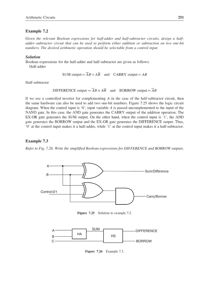
If we use a controlled inverter for complementing A in the case of the half-subtractor circuit, then
the same hardware can also be used to add two one-bit numbers. Figure 7.25 shows the logic circuit
diagram. When the control input is ‘0’, input variable A is passed uncomplemented to the input of the
NAND gate. In this case, the AND gate generates the CARRY output of the addition operation. The
EX-OR gate generates the SUM output. On the other hand, when the control input is ‘1’, the AND
gate generates the BORROW output and the EX-OR gate generates the DIFFERENCE output. Thus,
‘0’ at the control input makes it a half-adder, while ‘1’ at the control input makes it a half-subtractor.
Example 7.3
Refer to Fig. 7.26. Write the simplified Boolean expressions for DIFFERENCE and BORROW outputs.
Carry/Borrow
Sum/Difference
Control:0/1
A
B
Figure 7.25 Solution to example 7.2.
HA
A
B
C
BORROW
DIFFERENCE
HS
SUM
Figure 7.26 Example 7.3.
251
Example 7.2
Given the relevant Boolean expressions for half-adder and half-subtractor circuits, design a halfadder–subtractor circuit that can be used to perform either addition or subtraction on two one-bit
numbers. The desired arithmetic operation should be selectable from a control input.
Solution
Boolean expressions for the half-adder and half-subtractor are given as follows:
Half-adder
SUM output = AB + AB and CARRY output = AB
Half-subtractor
DIFFERENCE output = AB + AB and BORROW output = AB
If we use a controlled inverter for complementing A in the case of the half-subtractor circuit, then
the same hardware can also be used to add two one-bit numbers. Figure 7.25 shows the logic circuit
diagram. When the control input is ‘0’, input variable A is passed uncomplemented to the input of the
NAND gate. In this case, the AND gate generates the CARRY output of the addition operation. The
EX-OR gate generates the SUM output. On the other hand, when the control input is ‘1’, the AND
gate generates the BORROW output and the EX-OR gate generates the DIFFERENCE output. Thus,
‘0’ at the control input makes it a half-adder, while ‘1’ at the control input makes it a half-subtractor.
Example 7.3
Refer to Fig. 7.26. Write the simplified Boolean expressions for DIFFERENCE and BORROW outputs.
Carry/Borrow
Sum/Difference
Control:0/1
A
B
Figure 7.25 Solution to example 7.2.
HA
A
B
C
BORROW
DIFFERENCE
HS
SUM
Figure 7.26 Example 7.3.