

240
Digital Electronics
S
C in
C in
A
A
B
B
(a)
(b)
C in
C out
C in
A
B
B
A
A
A
B
B
C in
C in
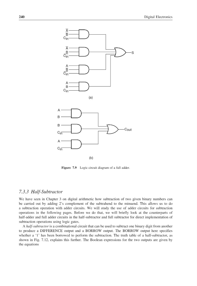
Figure 7.9 Logic circuit diagram of a full adder.
7.3.3 Half-Subtractor
We have seen in Chapter 3 on digital arithmetic how subtraction of two given binary numbers can
be carried out by adding 2’s complement of the subtrahend to the minuend. This allows us to do
a subtraction operation with adder circuits. We will study the use of adder circuits for subtraction
operations in the following pages. Before we do that, we will briefly look at the counterparts of
half-adder and full adder circuits in the half-subtractor and full subtractor for direct implementation of
subtraction operations using logic gates.
A half-subtractor is a combinational circuit that can be used to subtract one binary digit from another
to produce a DIFFERENCE output and a BORROW output. The BORROW output here specifies
whether a ‘1’ has been borrowed to perform the subtraction. The truth table of a half-subtractor, as
shown in Fig. 7.12, explains this further. The Boolean expressions for the two outputs are given by
the equations
Digital Electronics
S
C in
C in
A
A
B
B
(a)
(b)
C in
C out
C in
A
B
B
A
A
A
B
B
C in
C in
Figure 7.9 Logic circuit diagram of a full adder.
7.3.3 Half-Subtractor
We have seen in Chapter 3 on digital arithmetic how subtraction of two given binary numbers can
be carried out by adding 2’s complement of the subtrahend to the minuend. This allows us to do
a subtraction operation with adder circuits. We will study the use of adder circuits for subtraction
operations in the following pages. Before we do that, we will briefly look at the counterparts of
half-adder and full adder circuits in the half-subtractor and full subtractor for direct implementation of
subtraction operations using logic gates.
A half-subtractor is a combinational circuit that can be used to subtract one binary digit from another
to produce a DIFFERENCE output and a BORROW output. The BORROW output here specifies
whether a ‘1’ has been borrowed to perform the subtraction. The truth table of a half-subtractor, as
shown in Fig. 7.12, explains this further. The Boolean expressions for the two outputs are given by
the equations