

238
Digital Electronics
A
B
S
Full
Adder
Cin
C out
A
0
0
0
0
1
1
1
1
B
0
0
1
1
0
0
1
1
C
0
1
0
1
0
1
0
1
in
SUM (S)
0
1
1
0
1
0
0
1
C
0
0
0
1
0
1
1
1
out
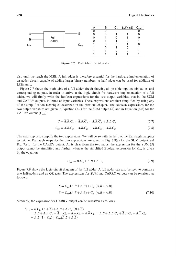
Figure 7.7 Truth table of a full adder.
also until we reach the MSB. A full adder is therefore essential for the hardware implementation of
an adder circuit capable of adding larger binary numbers. A half-adder can be used for addition of
LSBs only.
Figure 7.7 shows the truth table of a full adder circuit showing all possible input combinations and
corresponding outputs. In order to arrive at the logic circuit for hardware implementation of a full
adder, we will firstly write the Boolean expressions for the two output variables, that is, the SUM
and CARRY outputs, in terms of input variables. These expressions are then simplified by using any
of the simplification techniques described in the previous chapter. The Boolean expressions for the
two output variables are given in Equation (7.7) for the SUM output (S) and in Equation (6.6) for the
CARRY output (C out :
S = AABBC in + AABBC in + AABBC in + AABBC in
(7.7)
C out = AABBC in + AABBC in + AABBC in + AABBC in
(7.8)
The next step is to simplify the two expressions. We will do so with the help of the Karnaugh mapping
technique. Karnaugh maps for the two expressions are given in Fig. 7.8(a) for the SUM output and
Fig. 7.8(b) for the CARRY output. As is clear from the two maps, the expression for the SUM (SS
output cannot be simplified any further, whereas the simplified Boolean expression for C out is given
by the equation
C out = BBC in + AAB + AAC in
(7.9)
Figure 7.9 shows the logic circuit diagram of the full adder. A full adder can also be seen to comprise
two half-adders and an OR gate. The expressions for SUM and CARRY outputs can be rewritten as
follows:
S = C in AAB + AABB + C in AAB + AABB
S = C in AAB + AABB + C in AAB + AABB
(7.10)
Similarly, the expression for CARRY output can be rewritten as follows:
C out = BBC in A + AA + AAB + AAC in B + BB
= AAB + AABBC in + AABBC in + AABBC in + AABBC in = AAB + AABBC in + AABBC in + AABBC in
= AABBB1 + C in + C in AAB + AABB
Digital Electronics
A
B
S
Full
Adder
Cin
C out
A
0
0
0
0
1
1
1
1
B
0
0
1
1
0
0
1
1
C
0
1
0
1
0
1
0
1
in
SUM (S)
0
1
1
0
1
0
0
1
C
0
0
0
1
0
1
1
1
out
Figure 7.7 Truth table of a full adder.
also until we reach the MSB. A full adder is therefore essential for the hardware implementation of
an adder circuit capable of adding larger binary numbers. A half-adder can be used for addition of
LSBs only.
Figure 7.7 shows the truth table of a full adder circuit showing all possible input combinations and
corresponding outputs. In order to arrive at the logic circuit for hardware implementation of a full
adder, we will firstly write the Boolean expressions for the two output variables, that is, the SUM
and CARRY outputs, in terms of input variables. These expressions are then simplified by using any
of the simplification techniques described in the previous chapter. The Boolean expressions for the
two output variables are given in Equation (7.7) for the SUM output (S) and in Equation (6.6) for the
CARRY output (C out :
S = AABBC in + AABBC in + AABBC in + AABBC in
(7.7)
C out = AABBC in + AABBC in + AABBC in + AABBC in
(7.8)
The next step is to simplify the two expressions. We will do so with the help of the Karnaugh mapping
technique. Karnaugh maps for the two expressions are given in Fig. 7.8(a) for the SUM output and
Fig. 7.8(b) for the CARRY output. As is clear from the two maps, the expression for the SUM (SS
output cannot be simplified any further, whereas the simplified Boolean expression for C out is given
by the equation
C out = BBC in + AAB + AAC in
(7.9)
Figure 7.9 shows the logic circuit diagram of the full adder. A full adder can also be seen to comprise
two half-adders and an OR gate. The expressions for SUM and CARRY outputs can be rewritten as
follows:
S = C in AAB + AABB + C in AAB + AABB
S = C in AAB + AABB + C in AAB + AABB
(7.10)
Similarly, the expression for CARRY output can be rewritten as follows:
C out = BBC in A + AA + AAB + AAC in B + BB
= AAB + AABBC in + AABBC in + AABBC in + AABBC in = AAB + AABBC in + AABBC in + AABBC in
= AABBB1 + C in + C in AAB + AABB