

176
Digital Electronics
R
+V
Q 3
Q 4
Q 1
Q 2
A
A
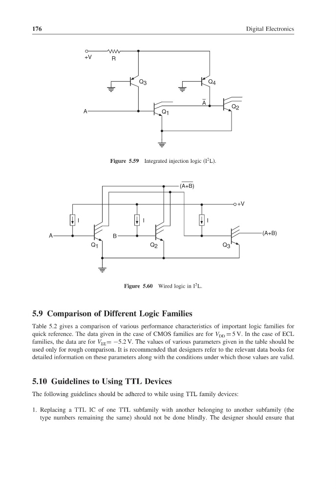
Figure 5.59 Integrated injection logic (I
2 L).
B
(A+B)
+V
I
I
I
Q 2
Q 3
(A+B)
Q 1
A
Figure 5.60 Wired logic in I
2 L.
5.9 Comparison of Different Logic Families
Table 5.2 gives a comparison of various performance characteristics of important logic families for
quick reference. The data given in the case of CMOS families are for V DD = 5 V. In the case of ECL
families, the data are for V EE = −5.2 V. The values of various parameters given in the table should be
used only for rough comparison. It is recommended that designers refer to the relevant data books for
detailed information on these parameters along with the conditions under which those values are valid.
5.10 Guidelines to Using TTL Devices
The following guidelines should be adhered to while using TTL family devices:
1. Replacing a TTL IC of one TTL subfamily with another belonging to another subfamily (the
type numbers remaining the same) should not be done blindly. The designer should ensure that
Digital Electronics
R
+V
Q 3
Q 4
Q 1
Q 2
A
A
Figure 5.59 Integrated injection logic (I
2 L).
B
(A+B)
+V
I
I
I
Q 2
Q 3
(A+B)
Q 1
A
Figure 5.60 Wired logic in I
2 L.
5.9 Comparison of Different Logic Families
Table 5.2 gives a comparison of various performance characteristics of important logic families for
quick reference. The data given in the case of CMOS families are for V DD = 5 V. In the case of ECL
families, the data are for V EE = −5.2 V. The values of various parameters given in the table should be
used only for rough comparison. It is recommended that designers refer to the relevant data books for
detailed information on these parameters along with the conditions under which those values are valid.
5.10 Guidelines to Using TTL Devices
The following guidelines should be adhered to while using TTL family devices:
1. Replacing a TTL IC of one TTL subfamily with another belonging to another subfamily (the
type numbers remaining the same) should not be done blindly. The designer should ensure that