

158
Digital Electronics
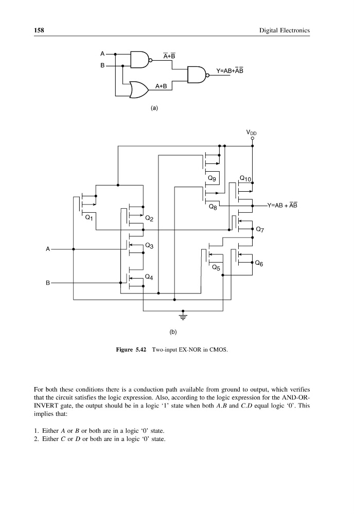
Figure 5.42 Two-input EX-NOR in CMOS.
For both these conditions there is a conduction path available from ground to output, which verifies
that the circuit satisfies the logic expression. Also, according to the logic expression for the AND-ORINVERT gate, the output should be in a logic ‘1’ state when both AAB and CCD equal logic ‘0’. This
implies that:
1. Either A or B or both are in a logic ‘0’ state.
2. Either C or D or both are in a logic ‘0’ state.
Digital Electronics
Figure 5.42 Two-input EX-NOR in CMOS.
For both these conditions there is a conduction path available from ground to output, which verifies
that the circuit satisfies the logic expression. Also, according to the logic expression for the AND-ORINVERT gate, the output should be in a logic ‘1’ state when both AAB and CCD equal logic ‘0’. This
implies that:
1. Either A or B or both are in a logic ‘0’ state.
2. Either C or D or both are in a logic ‘0’ state.