

Logic Families
157
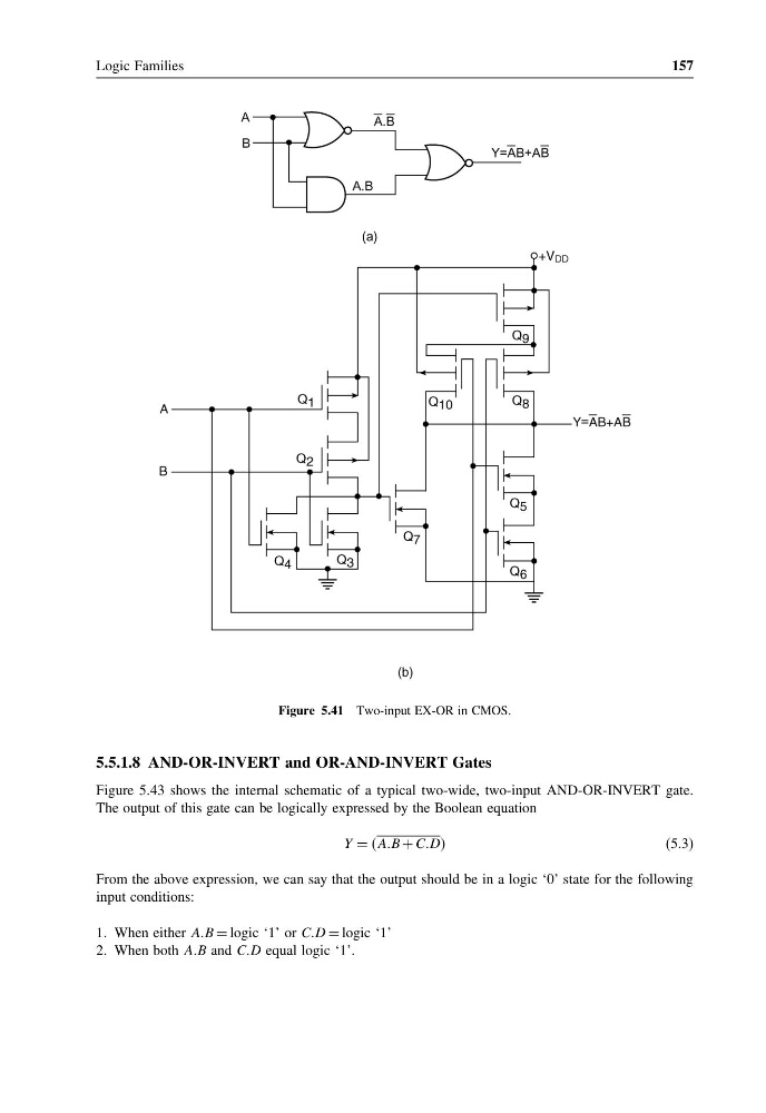
Figure 5.41 Two-input EX-OR in CMOS.
5.5.1.8 AND-OR-INVERT and OR-AND-INVERT Gates
Figure 5.43 shows the internal schematic of a typical two-wide, two-input AND-OR-INVERT gate.
The output of this gate can be logically expressed by the Boolean equation
Y = AAB + CCDD
(5.3)
From the above expression, we can say that the output should be in a logic ‘0’ state for the following
input conditions:
1. When either AAB = logic ‘1’ or CCD = logic ‘1’
2. When both AAB and CCD equal logic ‘1’.
157
Figure 5.41 Two-input EX-OR in CMOS.
5.5.1.8 AND-OR-INVERT and OR-AND-INVERT Gates
Figure 5.43 shows the internal schematic of a typical two-wide, two-input AND-OR-INVERT gate.
The output of this gate can be logically expressed by the Boolean equation
Y = AAB + CCDD
(5.3)
From the above expression, we can say that the output should be in a logic ‘0’ state for the following
input conditions:
1. When either AAB = logic ‘1’ or CCD = logic ‘1’
2. When both AAB and CCD equal logic ‘1’.