

Logic Families
143
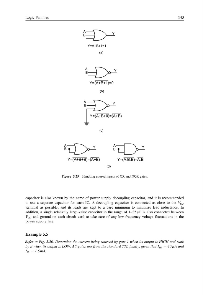
Figure 5.25 Handling unused inputs of OR and NOR gates.
capacitor is also known by the name of power supply decoupling capacitor, and it is recommended
to use a separate capacitor for each IC. A decoupling capacitor is connected as close to the V CC
terminal as possible, and its leads are kept to a bare minimum to minimize lead inductance. In
addition, a single relatively large-value capacitor in the range of 1–22 F is also connected between
V CC and ground on each circuit card to take care of any low-frequency voltage fluctuations in the
power supply line.
Example 5.5
Refer to Fig. 5.30. Determine the current being sourced by gate 1 when its output is HIGH and sunk
by it when its output is LOW. All gates are from the standard TTL family, given that I IH = 40 A and
I IL = 1.6 mA.
143
Figure 5.25 Handling unused inputs of OR and NOR gates.
capacitor is also known by the name of power supply decoupling capacitor, and it is recommended
to use a separate capacitor for each IC. A decoupling capacitor is connected as close to the V CC
terminal as possible, and its leads are kept to a bare minimum to minimize lead inductance. In
addition, a single relatively large-value capacitor in the range of 1–22 F is also connected between
V CC and ground on each circuit card to take care of any low-frequency voltage fluctuations in the
power supply line.
Example 5.5
Refer to Fig. 5.30. Determine the current being sourced by gate 1 when its output is HIGH and sunk
by it when its output is LOW. All gates are from the standard TTL family, given that I IH = 40 A and
I IL = 1.6 mA.