

Logic Gates and Related Devices
85
4.4 Universal Gates
OR, AND and NOT gates are the three basic logic gates as they together can be used to construct
the logic circuit for any given Boolean expression. NOR and NAND gates have the property that they
individually can be used to hardware-implement a logic circuit corresponding to any given Boolean
expression. That is, it is possible to use either only NAND gates or only NOR gates to implement any
Boolean expression. This is so because a combination of NAND gates or a combination of NOR gates
can be used to perform functions of any of the basic logic gates. It is for this reason that NAND and
NOR gates are universal gates.
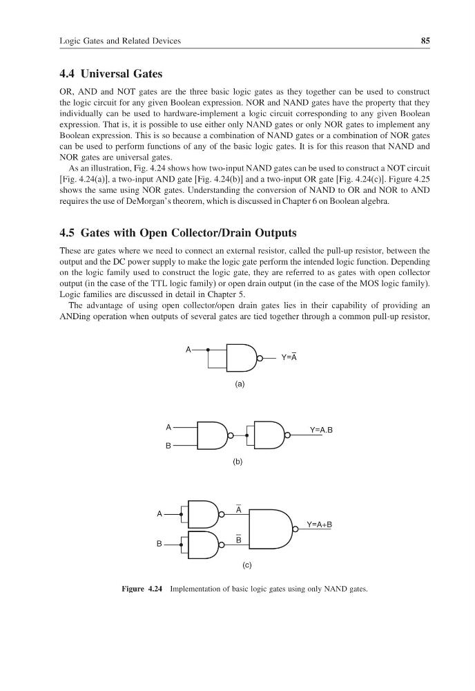
As an illustration, Fig. 4.24 shows how two-input NAND gates can be used to construct a NOT circuit
[Fig. 4.24(a)], a two-input AND gate [Fig. 4.24(b)] and a two-input OR gate [Fig. 4.24(c)]. Figure 4.25
shows the same using NOR gates. Understanding the conversion of NAND to OR and NOR to AND
requires the use of DeMorgan’s theorem, which is discussed in Chapter 6 on Boolean algebra.
4.5 Gates with Open Collector/Drain Outputs
These are gates where we need to connect an external resistor, called the pull-up resistor, between the
output and the DC power supply to make the logic gate perform the intended logic function. Depending
on the logic family used to construct the logic gate, they are referred to as gates with open collector
output (in the case of the TTL logic family) or open drain output (in the case of the MOS logic family).
Logic families are discussed in detail in Chapter 5.
The advantage of using open collector/open drain gates lies in their capability of providing an
ANDing operation when outputs of several gates are tied together through a common pull-up resistor,
Y=A
(a)
A
(b)
A
B
Y=A.B
A
B
A
B
Y=A+B
(c)
Figure 4.24 Implementation of basic logic gates using only NAND gates.
85
4.4 Universal Gates
OR, AND and NOT gates are the three basic logic gates as they together can be used to construct
the logic circuit for any given Boolean expression. NOR and NAND gates have the property that they
individually can be used to hardware-implement a logic circuit corresponding to any given Boolean
expression. That is, it is possible to use either only NAND gates or only NOR gates to implement any
Boolean expression. This is so because a combination of NAND gates or a combination of NOR gates
can be used to perform functions of any of the basic logic gates. It is for this reason that NAND and
NOR gates are universal gates.
As an illustration, Fig. 4.24 shows how two-input NAND gates can be used to construct a NOT circuit
[Fig. 4.24(a)], a two-input AND gate [Fig. 4.24(b)] and a two-input OR gate [Fig. 4.24(c)]. Figure 4.25
shows the same using NOR gates. Understanding the conversion of NAND to OR and NOR to AND
requires the use of DeMorgan’s theorem, which is discussed in Chapter 6 on Boolean algebra.
4.5 Gates with Open Collector/Drain Outputs
These are gates where we need to connect an external resistor, called the pull-up resistor, between the
output and the DC power supply to make the logic gate perform the intended logic function. Depending
on the logic family used to construct the logic gate, they are referred to as gates with open collector
output (in the case of the TTL logic family) or open drain output (in the case of the MOS logic family).
Logic families are discussed in detail in Chapter 5.
The advantage of using open collector/open drain gates lies in their capability of providing an
ANDing operation when outputs of several gates are tied together through a common pull-up resistor,
Y=A
(a)
A
(b)
A
B
Y=A.B
A
B
A
B
Y=A+B
(c)
Figure 4.24 Implementation of basic logic gates using only NAND gates.