

84 Basic Seismological Theory
Gas sand
α 4 , β 4
α ρ
α 3 , β 3
α ρ
α 2 , β 2
α ρ
T 12 R 23 T 21
R 12
T 12 T 23 R 34 T 32 T 21
time
R 14
2h 2 / 2
α
2h 3 / 3
α
R 12
T 12 R 23 T 21
T 12 T 23 R 34 T 32 T 21
R 14
Shale
α 1 , ρ 1
α ρ
h 2
h 3 Oil sand
Saltwater sand
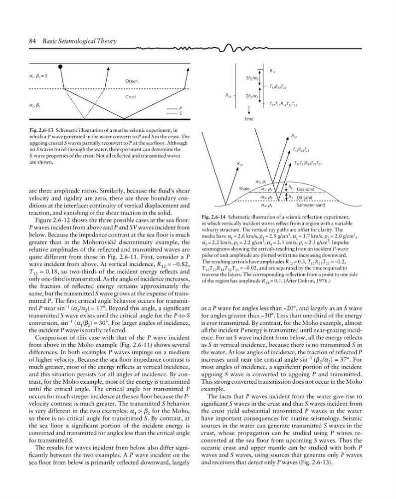
Fig. 2.6-14 Schematic illustration of a seismic reflection experiment,
in which vertically incident waves reflect from a region with a variable
velocity structure. The vertical ray paths are offset for clarity. The
media have α 1 = 2.6 km/s, ρ 1 = 2.5 g/cm
3 , α 2 = 1.7 km/s, ρ 2 = 2.0 g/cm
3 ,
α 3 = 2.2 km/s, ρ 3 = 2.2 g/cm 3 , α 4 = 2.3 km/s, ρ 4 = 2.3 g/cm 3 . Impulse
seismograms showing the arrivals resulting from an incident P-wave
pulse of unit amplitude are plotted with time increasing downward.
The resulting arrivals have amplitudes R 12 = 0.3, T 12 R 23 T 21 = −0.2,
T 12 T 23 R 34 T 32 T 21 = −0.02, and are separated by the time required to
traverse the layers. The corresponding reflection from a point to one side
of the region has amplitude R 14 = 0.1. (After Dobrin, 1976.)
1 , 1 = 0
Ocean
Crust
α β
2 , 2
α β
P
S
Fig. 2.6-13 Schematic illustration of a marine seismic experiment, in
which a P wave generated in the water converts to P and S in the crust. The
upgoing crustal S waves partially reconvert to P at the sea floor. Although
no S waves travel through the water, the experiment can determine the
S-wave properties of the crust. Not all reflected and transmitted waves
are shown.
are three amplitude ratios. Similarly, because the fluid’s shear
velocity and rigidity are zero, there are three boundary conditions at the interface: continuity of vertical displacement and
traction, and vanishing of the shear traction in the solid.
Figure 2.6-12 shows the three possible cases at the sea floor:
P waves incident from above and P and SV waves incident from
below. Because the impedance contrast at the sea floor is much
greater than in the Mohorovibia discontinuity example, the
relative amplitudes of the reflected and transmitted waves are
quite different from those in Fig. 2.6-11. First, consider a P
wave incident from above. At vertical incidence, R 12 = −0.82,
T 12 = 0.18, so two-thirds of the incident energy reflects and
only one-third is transmitted. As the angle of incidence increases,
the fraction of reflected energy remains approximately the
same, but the transmitted S wave grows at the expense of transmitted P. The first critical angle behavior occurs for transmitted P near sin
−1 (α 1 /α 2 ) = 17°. Beyond this angle, a significant
transmitted S wave exists until the critical angle for the P-to-S
conversion, sin −1 (α 1 /β 2 ) = 30°. For larger angles of incidence,
the incident P wave is totally reflected.
Comparison of this case with that of the P wave incident
from above in the Moho example (Fig. 2.6-11) shows several
differences. In both examples P waves impinge on a medium
of higher velocity. Because the sea floor impedance contrast is
much greater, most of the energy reflects at vertical incidence,
and this situation persists for all angles of incidence. By contrast, for the Moho example, most of the energy is transmitted
until the critical angle. The critical angle for transmitted P
occurs for much steeper incidence at the sea floor because the Pvelocity contrast is much greater. The transmitted S behavior
is very different in the two examples: α 1 > β 2 for the Moho,
so there is no critical angle for transmitted S. By contrast, at
the sea floor a significant portion of the incident energy is
converted and transmitted for angles less than the critical angle
for transmitted S.
The results for waves incident from below also differ significantly between the two examples. A P wave incident on the
sea floor from below is primarily reflected downward, largely
as a P wave for angles less than ~20°, and largely as an S wave
for angles greater than ~30°. Less than one-third of the energy
is ever transmitted. By contrast, for the Moho example, almost
all the incident P energy is transmitted until near-grazing incidence. For an S wave incident from below, all the energy reflects
as S at vertical incidence, because there is no transmitted S in
the water. At low angles of incidence, the fraction of reflected P
increases until near the critical angle sin −1 (β 2 /α 2 ) = 37°. For
most angles of incidence, a significant portion of the incident
upgoing S wave is converted to upgoing P and transmitted.
This strong converted transmission does not occur in the Moho
example.
The facts that P waves incident from the water give rise to
significant S waves in the crust and that S waves incident from
the crust yield substantial transmitted P waves in the water
have important consequences for marine seismology. Seismic
sources in the water can generate transmitted S waves in the
crust, whose propagation can be studied using P waves reconverted at the sea floor from upcoming S waves. Thus the
oceanic crust and upper mantle can be studied with both P
waves and S waves, using sources that generate only P waves
and receivers that detect only P waves (Fig. 2.6-13).
Gas sand
α 4 , β 4
α ρ
α 3 , β 3
α ρ
α 2 , β 2
α ρ
T 12 R 23 T 21
R 12
T 12 T 23 R 34 T 32 T 21
time
R 14
2h 2 / 2
α
2h 3 / 3
α
R 12
T 12 R 23 T 21
T 12 T 23 R 34 T 32 T 21
R 14
Shale
α 1 , ρ 1
α ρ
h 2
h 3 Oil sand
Saltwater sand
Fig. 2.6-14 Schematic illustration of a seismic reflection experiment,
in which vertically incident waves reflect from a region with a variable
velocity structure. The vertical ray paths are offset for clarity. The
media have α 1 = 2.6 km/s, ρ 1 = 2.5 g/cm
3 , α 2 = 1.7 km/s, ρ 2 = 2.0 g/cm
3 ,
α 3 = 2.2 km/s, ρ 3 = 2.2 g/cm 3 , α 4 = 2.3 km/s, ρ 4 = 2.3 g/cm 3 . Impulse
seismograms showing the arrivals resulting from an incident P-wave
pulse of unit amplitude are plotted with time increasing downward.
The resulting arrivals have amplitudes R 12 = 0.3, T 12 R 23 T 21 = −0.2,
T 12 T 23 R 34 T 32 T 21 = −0.02, and are separated by the time required to
traverse the layers. The corresponding reflection from a point to one side
of the region has amplitude R 14 = 0.1. (After Dobrin, 1976.)
1 , 1 = 0
Ocean
Crust
α β
2 , 2
α β
P
S
Fig. 2.6-13 Schematic illustration of a marine seismic experiment, in
which a P wave generated in the water converts to P and S in the crust. The
upgoing crustal S waves partially reconvert to P at the sea floor. Although
no S waves travel through the water, the experiment can determine the
S-wave properties of the crust. Not all reflected and transmitted waves
are shown.
are three amplitude ratios. Similarly, because the fluid’s shear
velocity and rigidity are zero, there are three boundary conditions at the interface: continuity of vertical displacement and
traction, and vanishing of the shear traction in the solid.
Figure 2.6-12 shows the three possible cases at the sea floor:
P waves incident from above and P and SV waves incident from
below. Because the impedance contrast at the sea floor is much
greater than in the Mohorovibia discontinuity example, the
relative amplitudes of the reflected and transmitted waves are
quite different from those in Fig. 2.6-11. First, consider a P
wave incident from above. At vertical incidence, R 12 = −0.82,
T 12 = 0.18, so two-thirds of the incident energy reflects and
only one-third is transmitted. As the angle of incidence increases,
the fraction of reflected energy remains approximately the
same, but the transmitted S wave grows at the expense of transmitted P. The first critical angle behavior occurs for transmitted P near sin
−1 (α 1 /α 2 ) = 17°. Beyond this angle, a significant
transmitted S wave exists until the critical angle for the P-to-S
conversion, sin −1 (α 1 /β 2 ) = 30°. For larger angles of incidence,
the incident P wave is totally reflected.
Comparison of this case with that of the P wave incident
from above in the Moho example (Fig. 2.6-11) shows several
differences. In both examples P waves impinge on a medium
of higher velocity. Because the sea floor impedance contrast is
much greater, most of the energy reflects at vertical incidence,
and this situation persists for all angles of incidence. By contrast, for the Moho example, most of the energy is transmitted
until the critical angle. The critical angle for transmitted P
occurs for much steeper incidence at the sea floor because the Pvelocity contrast is much greater. The transmitted S behavior
is very different in the two examples: α 1 > β 2 for the Moho,
so there is no critical angle for transmitted S. By contrast, at
the sea floor a significant portion of the incident energy is
converted and transmitted for angles less than the critical angle
for transmitted S.
The results for waves incident from below also differ significantly between the two examples. A P wave incident on the
sea floor from below is primarily reflected downward, largely
as a P wave for angles less than ~20°, and largely as an S wave
for angles greater than ~30°. Less than one-third of the energy
is ever transmitted. By contrast, for the Moho example, almost
all the incident P energy is transmitted until near-grazing incidence. For an S wave incident from below, all the energy reflects
as S at vertical incidence, because there is no transmitted S in
the water. At low angles of incidence, the fraction of reflected P
increases until near the critical angle sin −1 (β 2 /α 2 ) = 37°. For
most angles of incidence, a significant portion of the incident
upgoing S wave is converted to upgoing P and transmitted.
This strong converted transmission does not occur in the Moho
example.
The facts that P waves incident from the water give rise to
significant S waves in the crust and that S waves incident from
the crust yield substantial transmitted P waves in the water
have important consequences for marine seismology. Seismic
sources in the water can generate transmitted S waves in the
crust, whose propagation can be studied using P waves reconverted at the sea floor from upcoming S waves. Thus the
oceanic crust and upper mantle can be studied with both P
waves and S waves, using sources that generate only P waves
and receivers that detect only P waves (Fig. 2.6-13).