

have amplitude R 14 . The lateral variation in impedance contrasts causes a significant difference in the amplitude of the
reflected waves.
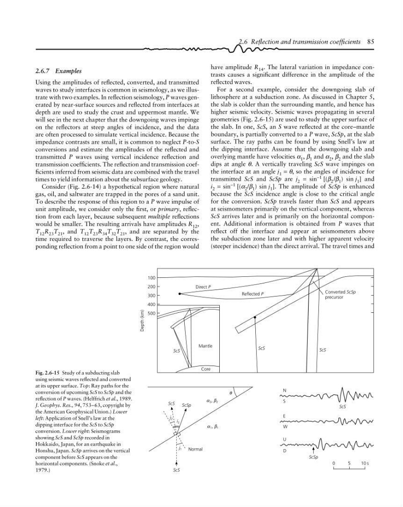
For a second example, consider the downgoing slab of
lithosphere at a subduction zone. As discussed in Chapter 5,
the slab is colder than the surrounding mantle, and hence has
higher seismic velocity. Seismic waves propagating in several
geometries (Fig. 2.6-15) are used to study the upper surface of
the slab. In one, ScS, an S wave reflected at the core–mantle
boundary, is partially converted to a P wave, ScSp, at the slab
surface. The ray paths can be found by using Snell’s law at
the dipping interface. Assume that the downgoing slab and
overlying mantle have velocities α 1 , β 1 and α 2 , β 2 and the slab
dips at angle θ. A vertically traveling ScS wave impinges on
the interface at an angle j 1 = θ, so the angles of incidence for
transmitted ScS and ScSp are j 2 = sin −1 [(β 2 /β 1 ) sin j 1 ] and
i 2 = sin −1 [(α 2 /β 1 ) sin j 1 ]. The amplitude of ScSp is enhanced
because the ScS incidence angle is close to the critical angle
for the conversion. ScSp travels faster than ScS and appears
at seismometers primarily on the vertical component, whereas
ScS arrives later and is primarily on the horizontal component. Additional information is obtained from P waves that
reflect off the interface and appear at seismometers above
the subduction zone later and with higher apparent velocity
(steeper incidence) than the direct arrival. The travel times and
2.6 Reflection and transmission coefficients 85
i 2
j 2
Depth (km)
100
200
300
400
500
ScS
Direct P
Reflected P
Converted ScSp
precursor
ScS
ScS
Mantle
Core
ScS
ScSp
θ
j 1 Normal
ScS
ScS
N
S
E
W
U
D
ScSp
0
5
1 0s
α 2 , β 2
α β
α 1 , β 1
α β
Fig. 2.6-15 Study of a subducting slab
using seismic waves reflected and converted
at its upper surface. Top: Ray paths for the
conversion of upcoming ScS to ScSp and the
reflection of P waves. (Helffrich et al., 1989.
J. Geophys. Res., 94, 753–63, copyright by
the American Geophysical Union.) Lower
left: Application of Snell’s law at the
dipping interface for the ScS to ScSp
conversion. Lower right: Seismograms
showing ScS and ScSp recorded in
Hokkaido, Japan, for an earthquake in
Honshu, Japan. ScSp arrives on the vertical
component before ScS appears on the
horizontal components. (Snoke et al.,
1979.)
2.6.7 Examples
Using the amplitudes of reflected, converted, and transmitted
waves to study interfaces is common in seismology, as we illustrate with two examples. In reflection seismology, P waves generated by near-surface sources and reflected from interfaces at
depth are used to study the crust and uppermost mantle. We
will see in the next chapter that the downgoing waves impinge
on the reflectors at steep angles of incidence, and the data
are often processed to simulate vertical incidence. Because the
impedance contrasts are small, it is common to neglect P-to-S
conversions and estimate the amplitudes of the reflected and
transmitted P waves using vertical incidence reflection and
transmission coefficients. The reflection and transmission coefficients inferred from seismic data are combined with the travel
times to yield information about the subsurface geology.
Consider (Fig. 2.6-14) a hypothetical region where natural
gas, oil, and saltwater are trapped in the pores of a sand unit.
To describe the response of this region to a P wave impulse of
unit amplitude, we consider only the first, or primary, reflection from each layer, because subsequent multiple reflections
would be smaller. The resulting arrivals have amplitudes R 12 ,
T 12 R 23 T 21 , and T 12 T 23 R 34 T 32 T 21 , and are separated by the
time required to traverse the layers. By contrast, the corresponding reflection from a point to one side of the region would
reflected waves.
For a second example, consider the downgoing slab of
lithosphere at a subduction zone. As discussed in Chapter 5,
the slab is colder than the surrounding mantle, and hence has
higher seismic velocity. Seismic waves propagating in several
geometries (Fig. 2.6-15) are used to study the upper surface of
the slab. In one, ScS, an S wave reflected at the core–mantle
boundary, is partially converted to a P wave, ScSp, at the slab
surface. The ray paths can be found by using Snell’s law at
the dipping interface. Assume that the downgoing slab and
overlying mantle have velocities α 1 , β 1 and α 2 , β 2 and the slab
dips at angle θ. A vertically traveling ScS wave impinges on
the interface at an angle j 1 = θ, so the angles of incidence for
transmitted ScS and ScSp are j 2 = sin −1 [(β 2 /β 1 ) sin j 1 ] and
i 2 = sin −1 [(α 2 /β 1 ) sin j 1 ]. The amplitude of ScSp is enhanced
because the ScS incidence angle is close to the critical angle
for the conversion. ScSp travels faster than ScS and appears
at seismometers primarily on the vertical component, whereas
ScS arrives later and is primarily on the horizontal component. Additional information is obtained from P waves that
reflect off the interface and appear at seismometers above
the subduction zone later and with higher apparent velocity
(steeper incidence) than the direct arrival. The travel times and
2.6 Reflection and transmission coefficients 85
i 2
j 2
Depth (km)
100
200
300
400
500
ScS
Direct P
Reflected P
Converted ScSp
precursor
ScS
ScS
Mantle
Core
ScS
ScSp
θ
j 1 Normal
ScS
ScS
N
S
E
W
U
D
ScSp
0
5
1 0s
α 2 , β 2
α β
α 1 , β 1
α β
Fig. 2.6-15 Study of a subducting slab
using seismic waves reflected and converted
at its upper surface. Top: Ray paths for the
conversion of upcoming ScS to ScSp and the
reflection of P waves. (Helffrich et al., 1989.
J. Geophys. Res., 94, 753–63, copyright by
the American Geophysical Union.) Lower
left: Application of Snell’s law at the
dipping interface for the ScS to ScSp
conversion. Lower right: Seismograms
showing ScS and ScSp recorded in
Hokkaido, Japan, for an earthquake in
Honshu, Japan. ScSp arrives on the vertical
component before ScS appears on the
horizontal components. (Snoke et al.,
1979.)
2.6.7 Examples
Using the amplitudes of reflected, converted, and transmitted
waves to study interfaces is common in seismology, as we illustrate with two examples. In reflection seismology, P waves generated by near-surface sources and reflected from interfaces at
depth are used to study the crust and uppermost mantle. We
will see in the next chapter that the downgoing waves impinge
on the reflectors at steep angles of incidence, and the data
are often processed to simulate vertical incidence. Because the
impedance contrasts are small, it is common to neglect P-to-S
conversions and estimate the amplitudes of the reflected and
transmitted P waves using vertical incidence reflection and
transmission coefficients. The reflection and transmission coefficients inferred from seismic data are combined with the travel
times to yield information about the subsurface geology.
Consider (Fig. 2.6-14) a hypothetical region where natural
gas, oil, and saltwater are trapped in the pores of a sand unit.
To describe the response of this region to a P wave impulse of
unit amplitude, we consider only the first, or primary, reflection from each layer, because subsequent multiple reflections
would be smaller. The resulting arrivals have amplitudes R 12 ,
T 12 R 23 T 21 , and T 12 T 23 R 34 T 32 T 21 , and are separated by the
time required to traverse the layers. By contrast, the corresponding reflection from a point to one side of the region would