

Incident
+z
Transmitted
T 12 = 1 + R 12 = u z
R 12 = u z
1 = u z
Reflected
1
0.5
0
−0.5
−1
20
0
4 0
6 0
8 0
Angle of incidence (°)
α = 6.8 km/s
β = 4.0 km/s
α
β
Reflected P
coefficient
energy ratio
Reflected SV
coefficient
energy ratio
Fig. 2.6-8 For a P wave incident on a free surface, potential reflection and
transmission coefficients and the ratios of reflected and transmitted energy
fluxes to that of the incident wave are shown as functions of the angle of
incidence of the incident P wave.
2.6 Reflection and transmission coefficients 81
of angles over which most of the energy reflects as SV. At two
angles, the incident P wave converts entirely to SV.
2.6.6 Solid–solid and solid–liquid interfaces
The approach we used for P–SV waves at a free surface can be
extended to a solid–solid interface. Consider the usual geometry (Fig. 2.6-9) in which P–SV waves propagating in the x–z
plane interact with a horizontal interface at z = 0. An incident
wave generates two reflected waves and two transmitted waves.
The four ratios of the amplitudes of the reflected P and SV and
transmitted P and SV waves to that of the incident wave are
found from the boundary conditions. There are four equations
because the x and z components of the displacement and traction are continuous at the interface. The resulting solutions are
complicated and are not given here. Instead, we consider some
general principles and examples.
Fig. 2.6-9 Geometry for a P wave incident on a solid–solid interface. A 1 ,
A 2 , B 2 , A′, and B′ are the amplitudes of the incident P wave, the reflected P
and SV waves, and the transmitted P and SV waves.
P
S
z
A 1
j 1
B 2
A 2
i 1
i 1
i 2
j 2
B′
A′
x
α 1 , β 1 , ρ 1
α β ρ
α 2 , β 2 , ρ 2
α β ρ
The solutions are simple for vertical incidence. For a vertically incident P wave, no SV waves are generated. The displacement is only in the z direction, and the ratio of the displacement
of the transmitted P wave to that of the incident wave is
( )
( )
.
u
u
T
z T
z I
=
=
+
12
1 1
1 1
2 2
2ρ α
ρ α
ρ α
(41)
The corresponding ratio for the reflected P wave is
( )
( )
.
u
u
R
z R
z I
=
=
−
+
12
1 1
2 2
1 1
2 2
ρ α
ρ α
ρ α
ρ α
(42)
These ratios, the vertical incidence transmission and reflection
coefficients for displacements, satisfy 1 + R 12 = T 12 , as required
by continuity of displacements. As for the SH case (Section
2.6.2), the vertical incidence transmission and reflection coefficients depend only on the acoustic impedances. For the incident
SV case, no P waves are generated, and the ratios of the displacement component u x have the same form, but in terms of
the shear velocity β.
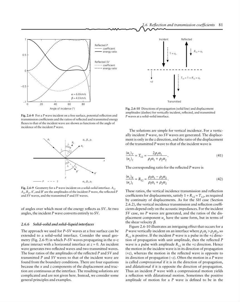
Figure 2.6-10 illustrates an intriguing effect that occurs for a
P wave vertically incident on an interface where ρ 1 α 1 > ρ 2 α 2 , so
R 12 is positive. If the incident P wave is a pulse in the +z direction of propagation with unit amplitude, then the reflected P
wave is a pulse with amplitude R 12 in the +z direction. Hence
the motion in the incident wave is in its direction of propagation
(+z), whereas the motion in the reflected wave is opposite to
its direction of propagation (−z). Often the motion in a P wave
is called compressional if it is in the direction of propagation,
and dilatational if it is opposite the direction of propagation.
Thus an incident P wave with a compressional motion yields
a reflection with dilatational motion. Sometimes the positive
amplitude of motion for a P wave is defined to be in the
Fig. 2.6-10 Directions of propagation (solid line) and displacement
amplitudes (dashes) for vertically incident, reflected, and transmitted
P waves at a solid–solid interface.
+z
Transmitted
T 12 = 1 + R 12 = u z
R 12 = u z
1 = u z
Reflected
1
0.5
0
−0.5
−1
20
0
4 0
6 0
8 0
Angle of incidence (°)
α = 6.8 km/s
β = 4.0 km/s
α
β
Reflected P
coefficient
energy ratio
Reflected SV
coefficient
energy ratio
Fig. 2.6-8 For a P wave incident on a free surface, potential reflection and
transmission coefficients and the ratios of reflected and transmitted energy
fluxes to that of the incident wave are shown as functions of the angle of
incidence of the incident P wave.
2.6 Reflection and transmission coefficients 81
of angles over which most of the energy reflects as SV. At two
angles, the incident P wave converts entirely to SV.
2.6.6 Solid–solid and solid–liquid interfaces
The approach we used for P–SV waves at a free surface can be
extended to a solid–solid interface. Consider the usual geometry (Fig. 2.6-9) in which P–SV waves propagating in the x–z
plane interact with a horizontal interface at z = 0. An incident
wave generates two reflected waves and two transmitted waves.
The four ratios of the amplitudes of the reflected P and SV and
transmitted P and SV waves to that of the incident wave are
found from the boundary conditions. There are four equations
because the x and z components of the displacement and traction are continuous at the interface. The resulting solutions are
complicated and are not given here. Instead, we consider some
general principles and examples.
Fig. 2.6-9 Geometry for a P wave incident on a solid–solid interface. A 1 ,
A 2 , B 2 , A′, and B′ are the amplitudes of the incident P wave, the reflected P
and SV waves, and the transmitted P and SV waves.
P
S
z
A 1
j 1
B 2
A 2
i 1
i 1
i 2
j 2
B′
A′
x
α 1 , β 1 , ρ 1
α β ρ
α 2 , β 2 , ρ 2
α β ρ
The solutions are simple for vertical incidence. For a vertically incident P wave, no SV waves are generated. The displacement is only in the z direction, and the ratio of the displacement
of the transmitted P wave to that of the incident wave is
( )
( )
.
u
u
T
z T
z I
=
=
+
12
1 1
1 1
2 2
2ρ α
ρ α
ρ α
(41)
The corresponding ratio for the reflected P wave is
( )
( )
.
u
u
R
z R
z I
=
=
−
+
12
1 1
2 2
1 1
2 2
ρ α
ρ α
ρ α
ρ α
(42)
These ratios, the vertical incidence transmission and reflection
coefficients for displacements, satisfy 1 + R 12 = T 12 , as required
by continuity of displacements. As for the SH case (Section
2.6.2), the vertical incidence transmission and reflection coefficients depend only on the acoustic impedances. For the incident
SV case, no P waves are generated, and the ratios of the displacement component u x have the same form, but in terms of
the shear velocity β.
Figure 2.6-10 illustrates an intriguing effect that occurs for a
P wave vertically incident on an interface where ρ 1 α 1 > ρ 2 α 2 , so
R 12 is positive. If the incident P wave is a pulse in the +z direction of propagation with unit amplitude, then the reflected P
wave is a pulse with amplitude R 12 in the +z direction. Hence
the motion in the incident wave is in its direction of propagation
(+z), whereas the motion in the reflected wave is opposite to
its direction of propagation (−z). Often the motion in a P wave
is called compressional if it is in the direction of propagation,
and dilatational if it is opposite the direction of propagation.
Thus an incident P wave with a compressional motion yields
a reflection with dilatational motion. Sometimes the positive
amplitude of motion for a P wave is defined to be in the
Fig. 2.6-10 Directions of propagation (solid line) and displacement
amplitudes (dashes) for vertically incident, reflected, and transmitted
P waves at a solid–solid interface.