

78 Basic Seismological Theory
To see the effect on the transmitted wave of an apparent
velocity less than that of medium 2, recall that the transmitted
wave (Eqn 2) is described by
u +
y (x, z, t) = B′ exp (i(ωt − k x x − k x r β 2 z)).
(18)
If c x < β 2 , the quantity (Eqn 2.5.8)
r β 2 = (c 2
x /β 2
2 − 1) 1/2
(19)
becomes an imaginary number. As a result, k x r β 2 , the z component of the wavenumber, also becomes imaginary, so Eqn 18
no longer describes a plane wave propagating in the +z direction. The square root, which describes the imaginary number,
has two possible signs. We pick the negative sign and define
r β 2 = −ir* β 2 , r* β 2 = (1 − c 2
x /β 2
2 ) 1/2
(20)
so that the z term in the displacement,
exp (−ik x r β 2 z) = exp (−k x r* β 2 z),
(21)
decays exponentially away from the interface in medium 2 as
z → ∞. Thus, instead of being a propagating wave, the transmitted wave becomes an evanescent or inhomogeneous wave
“trapped” near the interface. Choosing the negative sign in
Eqn 20 is a radiation boundary condition, because the opposite
choice gives displacement increasing with depth as z → ∞, as if
energy originated there.
The behavior of the reflected wave for postcritical incidence
results from the fact that the reflection coefficient (Eqn 9)
becomes a complex number. Using Eqn 20 shows that
R
r
i r
r
i r
12
1
2
1
2
1
2
1
2
=
+
−
*
*
.
µ
µ
µ
µ
β
β
β
β
(22)
This a complex number divided by its conjugate, so the magnitude of the reflection coefficient is 1, but there is a phase shift
of 2ε :
R 12 = e i2ε , ε
µ
µ
β
β
tan
*
.
=
−1 2
1
2
1
r
r
(23)
The phase shift depends on the angle of incidence. At critical
incidence, c x = β 2 , so r* β 2 = 0 and ε = 0°. As the angle of incidence
increases beyond critical, ε increases until grazing incidence,
j 1 = 90°, where c x = β 1 , r β 1 = 0, and ε = 90°. A 90° phase shift
turns a sine wave into a cosine wave, and vice versa, whereas a
180° phase shift is multiplication by −1. If the incident wave is
made up of different frequencies, the phase shift affects each
frequency, so the reflected wave can be computed using the
Fourier transform. Figure 2.6-5 illustrates how the reflected
wave would appear due to different phase shifts.
1 The wave angles and amplitudes can be shown by a simple experiment using
beams of light (Klosko et al., 2000).
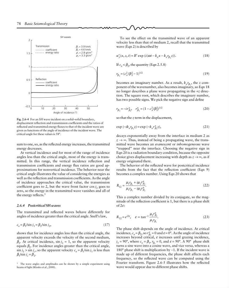
Fig. 2.6-4 For an SH wave incident on a solid–solid boundary,
displacement reflection and transmission coefficients and the ratios of
reflected and transmitted energy fluxes to that of the incident wave are
given as functions of the angle of incidence of the incident wave. The
critical angle for these values is 58°.
sum to one, so, as the reflected energy increases, the transmitted
energy decreases.
At vertical incidence and for most of the range of incidence
angles less than the critical angle, most of the energy is transmitted. In this range, the vertical incidence reflection and
transmission coefficients and energy flux ratios are good approximations for nonvertical incidence. The behavior near the
critical angle illustrates the value of considering the energies as
well as the reflection and transmission coefficients. As the angle
of incidence approaches the critical value, the transmission
coefficient goes to 2, but the wave front factor cos j 2 goes to
zero, so the energy in the transmitted wave vanishes and all of
the energy reflects. 1
2.6.4 Postcritical SH waves
The transmitted and reflected waves behave differently for
angles of incidence greater than the critical angle. Snell’s law,
c x = β 1 /sin j 1 = β 2 /sin j 2 ,
(17)
shows that for incidence angles less than the critical angle, the
apparent velocity exceeds the velocity of the second medium,
β 2 . At critical incidence, sin j 2 = 1, so the apparent velocity
equals β 2 . For incidence angles greater than the critical angle,
sin j 1 > sin j c , so the apparent velocity c x = β 1 /sin j 1 is less than
β 1 /sin j c = β 2 .
Transmission
2
1.5
1
0.5
0
−0.5
SH waves
coefficient
Reflection
coefficient
0
1 = 3.9 km/s
β
2 = 4.6 km/s
β
1 = 2.8 g/cm
3
ρ
2 = 3.3 g/cm
3
ρ
10
20
40
50
30
Angle of incidence (°)
energy ratio
energy ratio
To see the effect on the transmitted wave of an apparent
velocity less than that of medium 2, recall that the transmitted
wave (Eqn 2) is described by
u +
y (x, z, t) = B′ exp (i(ωt − k x x − k x r β 2 z)).
(18)
If c x < β 2 , the quantity (Eqn 2.5.8)
r β 2 = (c 2
x /β 2
2 − 1) 1/2
(19)
becomes an imaginary number. As a result, k x r β 2 , the z component of the wavenumber, also becomes imaginary, so Eqn 18
no longer describes a plane wave propagating in the +z direction. The square root, which describes the imaginary number,
has two possible signs. We pick the negative sign and define
r β 2 = −ir* β 2 , r* β 2 = (1 − c 2
x /β 2
2 ) 1/2
(20)
so that the z term in the displacement,
exp (−ik x r β 2 z) = exp (−k x r* β 2 z),
(21)
decays exponentially away from the interface in medium 2 as
z → ∞. Thus, instead of being a propagating wave, the transmitted wave becomes an evanescent or inhomogeneous wave
“trapped” near the interface. Choosing the negative sign in
Eqn 20 is a radiation boundary condition, because the opposite
choice gives displacement increasing with depth as z → ∞, as if
energy originated there.
The behavior of the reflected wave for postcritical incidence
results from the fact that the reflection coefficient (Eqn 9)
becomes a complex number. Using Eqn 20 shows that
R
r
i r
r
i r
12
1
2
1
2
1
2
1
2
=
+
−
*
*
.
µ
µ
µ
µ
β
β
β
β
(22)
This a complex number divided by its conjugate, so the magnitude of the reflection coefficient is 1, but there is a phase shift
of 2ε :
R 12 = e i2ε , ε
µ
µ
β
β
tan
*
.
=
−1 2
1
2
1
r
r
(23)
The phase shift depends on the angle of incidence. At critical
incidence, c x = β 2 , so r* β 2 = 0 and ε = 0°. As the angle of incidence
increases beyond critical, ε increases until grazing incidence,
j 1 = 90°, where c x = β 1 , r β 1 = 0, and ε = 90°. A 90° phase shift
turns a sine wave into a cosine wave, and vice versa, whereas a
180° phase shift is multiplication by −1. If the incident wave is
made up of different frequencies, the phase shift affects each
frequency, so the reflected wave can be computed using the
Fourier transform. Figure 2.6-5 illustrates how the reflected
wave would appear due to different phase shifts.
1 The wave angles and amplitudes can be shown by a simple experiment using
beams of light (Klosko et al., 2000).
Fig. 2.6-4 For an SH wave incident on a solid–solid boundary,
displacement reflection and transmission coefficients and the ratios of
reflected and transmitted energy fluxes to that of the incident wave are
given as functions of the angle of incidence of the incident wave. The
critical angle for these values is 58°.
sum to one, so, as the reflected energy increases, the transmitted
energy decreases.
At vertical incidence and for most of the range of incidence
angles less than the critical angle, most of the energy is transmitted. In this range, the vertical incidence reflection and
transmission coefficients and energy flux ratios are good approximations for nonvertical incidence. The behavior near the
critical angle illustrates the value of considering the energies as
well as the reflection and transmission coefficients. As the angle
of incidence approaches the critical value, the transmission
coefficient goes to 2, but the wave front factor cos j 2 goes to
zero, so the energy in the transmitted wave vanishes and all of
the energy reflects. 1
2.6.4 Postcritical SH waves
The transmitted and reflected waves behave differently for
angles of incidence greater than the critical angle. Snell’s law,
c x = β 1 /sin j 1 = β 2 /sin j 2 ,
(17)
shows that for incidence angles less than the critical angle, the
apparent velocity exceeds the velocity of the second medium,
β 2 . At critical incidence, sin j 2 = 1, so the apparent velocity
equals β 2 . For incidence angles greater than the critical angle,
sin j 1 > sin j c , so the apparent velocity c x = β 1 /sin j 1 is less than
β 1 /sin j c = β 2 .
Transmission
2
1.5
1
0.5
0
−0.5
SH waves
coefficient
Reflection
coefficient
0
1 = 3.9 km/s
β
2 = 4.6 km/s
β
1 = 2.8 g/cm
3
ρ
2 = 3.3 g/cm
3
ρ
10
20
40
50
30
Angle of incidence (°)
energy ratio
energy ratio