

Thus the reflection and transmission coefficients depend
on the acoustic impedances ρ i β i , as did those for waves on a
string (Section 2.2.3), but with an angle dependence that could
not occur for a one-dimensional string. If the media are interchanged, the reflection coefficient reverses polarity, R 12 = −R 21 ,
and the transmission coefficients satisfy T 12 + T 21 = 2. Due to
the displacement continuity condition (Eqn 3), 1 + R 12 = T 12 .
Large impedance contrasts favor reflection, whereas small contrasts favor transmission. In the limit of identical media there is
no reflection (R 12 = 0), and everything is transmitted (T 12 = 1).
An interesting effect occurs for an SH wave incident on the
earth’s free surface. Because β 2 = 0, the reflection coefficient
equals 1 regardless of the incidence angle, so the displacement is twice that of the upgoing wave. This also occurs at
solid–liquid interfaces, such as the sea floor or the core–mantle
boundary, which act as free surfaces for SH because no SH
waves propagate in the liquid.
The transmission and reflection coefficients have a particularly simple form for vertical incidence (j 1 = j 2 = 0):
T
R
12
1
1
2
12
1
2
1
2
=
+
=
−
+
,
.
2 1
1
2
1
2
1
2
ρ β
ρ β
ρ β
ρ β
ρ β
ρ β
ρ β
(12)
These vertical incidence forms are easy to remember and are a
useful approximation for nonvertical incidence.
The fact that the transmission and reflection coefficients
depend on the contrast in both density and velocity, whereas
the angles made by the waves depend only on velocity, makes
the amplitudes valuable for studying elastic properties from
seismological observations. Although each medium has three
quantities of interest, β i , µ i , and ρ i , only two are independent,
because the velocities depend on the rigidities and densities. For
example, if we regard the velocity and rigidity as independent,
the angles of reflection and transmission give information about
the velocity, and the amplitudes provide additional information about the rigidity.
2.6.3 Energy flux for reflected and transmitted SH waves
In some cases the transmission coefficient exceeds 1. For example, when an SH wave impinges on a higher-velocity medium
at critical incidence, the transmitted wave becomes horizontal
(j 2 = 90°) and Eqn 11 shows that the transmission coefficient is
2. As for the string (Section 2.2.4), this puzzling effect can be
explained by examining how the incident wave energy divides
between the reflected and transmitted waves.
We saw (Section 2.4.5) that the flux of energy per unit wave
front in the propagation direction associated with a harmonic
SH plane wave u(x, t) = A cos (ωt − kx) is the product of the
energy density and the velocity
0 = A 2 ω 2 ρβ/2.
(13)
Because no energy accumulates at an interface, the flux of
energy in the length of wave front incident on an element dx of
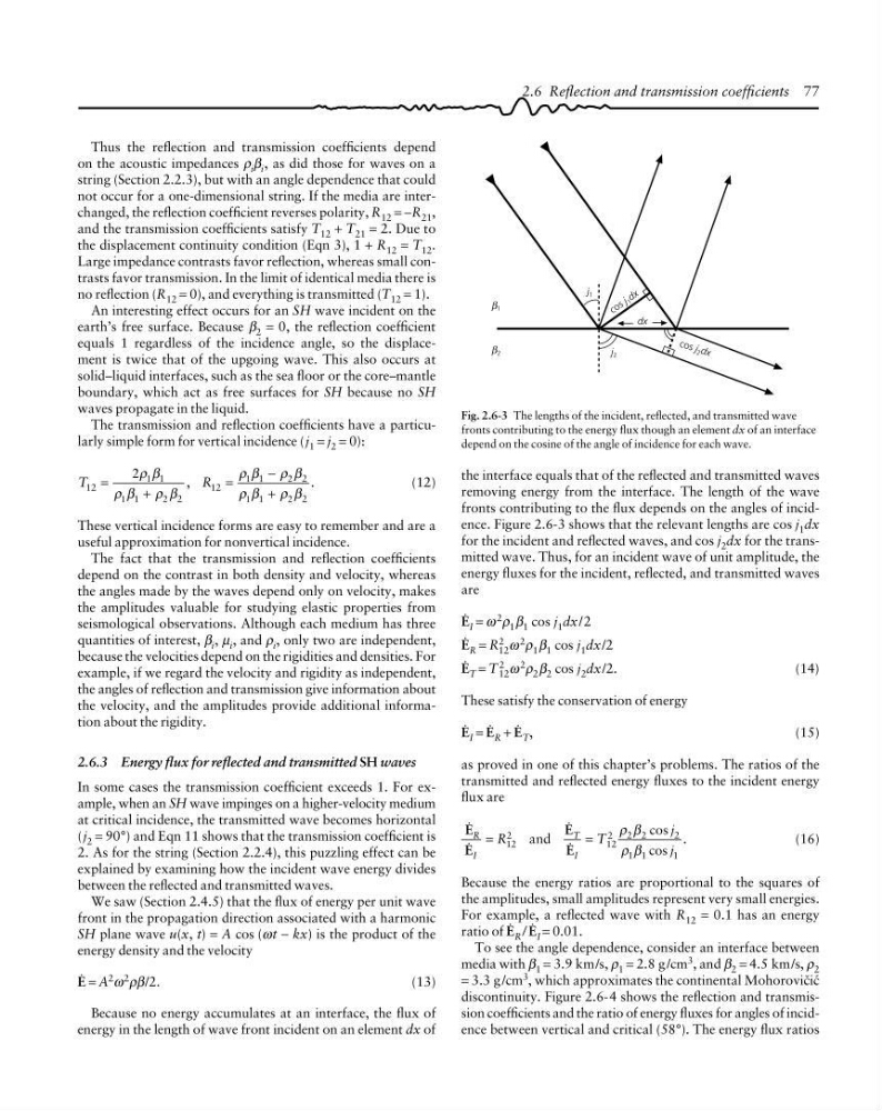
Fig. 2.6-3 The lengths of the incident, reflected, and transmitted wave
fronts contributing to the energy flux though an element dx of an interface
depend on the cosine of the angle of incidence for each wave.
2.6 Reflection and transmission coefficients 77
c o s j 1 d x
co s j 2 d x
dx
j 2
j 1
1
β
2
β
the interface equals that of the reflected and transmitted waves
removing energy from the interface. The length of the wave
fronts contributing to the flux depends on the angles of incidence. Figure 2.6-3 shows that the relevant lengths are cos j 1 dx
for the incident and reflected waves, and cos j 2 dx for the transmitted wave. Thus, for an incident wave of unit amplitude, the
energy fluxes for the incident, reflected, and transmitted waves
are
0 I = ω 2 ρ 1 β 1 cos j 1 dx/2
0 R = R
2
12 ω
2
ρ 1 β 1 cos j 1 dx/2
0 T = T
2
12 ω
2
ρ 2 β 2 cos j 2 dx/2.
(14)
These satisfy the conservation of energy
0 I = 0 R + 0 T ,
(15)
as proved in one of this chapter’s problems. The ratios of the
transmitted and reflected energy fluxes to the incident energy
flux are
0
0
0
0
R
I
T
I
R
T
j
j
cos
cos
.
=
=
12
2
12
2
2 2
2
1 1
1
and
ρ β
ρ β
(16)
Because the energy ratios are proportional to the squares of
the amplitudes, small amplitudes represent very small energies.
For example, a reflected wave with R 12 = 0.1 has an energy
ratio of 0 R / 0 I = 0.01.
To see the angle dependence, consider an interface between
media with β 1 = 3.9 km/s, ρ 1 = 2.8 g /cm 3 , and β 2 = 4.5 km/s, ρ 2
= 3.3 g /cm 3 , which approximates the continental Mohorovibia
discontinuity. Figure 2.6-4 shows the reflection and transmission coefficients and the ratio of energy fluxes for angles of incidence between vertical and critical (58°). The energy flux ratios
on the acoustic impedances ρ i β i , as did those for waves on a
string (Section 2.2.3), but with an angle dependence that could
not occur for a one-dimensional string. If the media are interchanged, the reflection coefficient reverses polarity, R 12 = −R 21 ,
and the transmission coefficients satisfy T 12 + T 21 = 2. Due to
the displacement continuity condition (Eqn 3), 1 + R 12 = T 12 .
Large impedance contrasts favor reflection, whereas small contrasts favor transmission. In the limit of identical media there is
no reflection (R 12 = 0), and everything is transmitted (T 12 = 1).
An interesting effect occurs for an SH wave incident on the
earth’s free surface. Because β 2 = 0, the reflection coefficient
equals 1 regardless of the incidence angle, so the displacement is twice that of the upgoing wave. This also occurs at
solid–liquid interfaces, such as the sea floor or the core–mantle
boundary, which act as free surfaces for SH because no SH
waves propagate in the liquid.
The transmission and reflection coefficients have a particularly simple form for vertical incidence (j 1 = j 2 = 0):
T
R
12
1
1
2
12
1
2
1
2
=
+
=
−
+
,
.
2 1
1
2
1
2
1
2
ρ β
ρ β
ρ β
ρ β
ρ β
ρ β
ρ β
(12)
These vertical incidence forms are easy to remember and are a
useful approximation for nonvertical incidence.
The fact that the transmission and reflection coefficients
depend on the contrast in both density and velocity, whereas
the angles made by the waves depend only on velocity, makes
the amplitudes valuable for studying elastic properties from
seismological observations. Although each medium has three
quantities of interest, β i , µ i , and ρ i , only two are independent,
because the velocities depend on the rigidities and densities. For
example, if we regard the velocity and rigidity as independent,
the angles of reflection and transmission give information about
the velocity, and the amplitudes provide additional information about the rigidity.
2.6.3 Energy flux for reflected and transmitted SH waves
In some cases the transmission coefficient exceeds 1. For example, when an SH wave impinges on a higher-velocity medium
at critical incidence, the transmitted wave becomes horizontal
(j 2 = 90°) and Eqn 11 shows that the transmission coefficient is
2. As for the string (Section 2.2.4), this puzzling effect can be
explained by examining how the incident wave energy divides
between the reflected and transmitted waves.
We saw (Section 2.4.5) that the flux of energy per unit wave
front in the propagation direction associated with a harmonic
SH plane wave u(x, t) = A cos (ωt − kx) is the product of the
energy density and the velocity
0 = A 2 ω 2 ρβ/2.
(13)
Because no energy accumulates at an interface, the flux of
energy in the length of wave front incident on an element dx of
Fig. 2.6-3 The lengths of the incident, reflected, and transmitted wave
fronts contributing to the energy flux though an element dx of an interface
depend on the cosine of the angle of incidence for each wave.
2.6 Reflection and transmission coefficients 77
c o s j 1 d x
co s j 2 d x
dx
j 2
j 1
1
β
2
β
the interface equals that of the reflected and transmitted waves
removing energy from the interface. The length of the wave
fronts contributing to the flux depends on the angles of incidence. Figure 2.6-3 shows that the relevant lengths are cos j 1 dx
for the incident and reflected waves, and cos j 2 dx for the transmitted wave. Thus, for an incident wave of unit amplitude, the
energy fluxes for the incident, reflected, and transmitted waves
are
0 I = ω 2 ρ 1 β 1 cos j 1 dx/2
0 R = R
2
12 ω
2
ρ 1 β 1 cos j 1 dx/2
0 T = T
2
12 ω
2
ρ 2 β 2 cos j 2 dx/2.
(14)
These satisfy the conservation of energy
0 I = 0 R + 0 T ,
(15)
as proved in one of this chapter’s problems. The ratios of the
transmitted and reflected energy fluxes to the incident energy
flux are
0
0
0
0
R
I
T
I
R
T
j
j
cos
cos
.
=
=
12
2
12
2
2 2
2
1 1
1
and
ρ β
ρ β
(16)
Because the energy ratios are proportional to the squares of
the amplitudes, small amplitudes represent very small energies.
For example, a reflected wave with R 12 = 0.1 has an energy
ratio of 0 R / 0 I = 0.01.
To see the angle dependence, consider an interface between
media with β 1 = 3.9 km/s, ρ 1 = 2.8 g /cm 3 , and β 2 = 4.5 km/s, ρ 2
= 3.3 g /cm 3 , which approximates the continental Mohorovibia
discontinuity. Figure 2.6-4 shows the reflection and transmission coefficients and the ratio of energy fluxes for angles of incidence between vertical and critical (58°). The energy flux ratios