

76 Basic Seismological Theory
Medium 1
B 2
Medium 2
B 1
j 1
j 1
j 2
z
B′
x
β 2 , ρ 2 , µ 2
ρ
β
µ
β 1 , ρ 1 , µ 1
ρ
β
µ
The other condition comes from the requirement that the
traction vector, T i = σ ij n j , be continuous. Because the unit
normal vector for the interface is (0, 0, 1), the stress components σ xz , σ yz , σ zz are continuous. For SH waves u x and u z are
zero, so σ xz = σ zz = 0, and σ yz is continuous. To use this condition we substitute
σ
µ
µ
µ
yz
yz
y
z
y
e
u
z
u
y
u
z
=
=
+
⎛
⎝
⎜ ⎜
⎞
⎠
⎟ ⎟
=
⎛
⎝
⎜ ⎜
⎞
⎠
⎟ ⎟
.
2
∂
∂
∂
∂
∂
∂
(5)
At points infinitesimally above and below the interface z = 0,
the stress satisfies
σ −
yz (x, 0, t) = σ +
yz (x, 0, t),
µ 1 ik x r β 1 (B 2 − B 1 ) exp (i(ωt − k x x))
= −µ 2 ik x r β 2 B′ exp (i(ωt − k x x)).
(6)
Canceling the factors common to both sides gives the second
condition
(B 1 − B 2 ) = B′(µ 2 r β 2 )/(µ 1 r β 1 ).
(7)
Solving Eqns 4 and 7 simultaneously yields the amplitudes of
the reflected and transmitted waves. First, we eliminate B 2 and
find the transmission coefficient,
T
B
B
r
r
r
12
1
1
1
2
=
=
+
,
′
2 1
1
2
µ
µ
µ
β
β
β
(8)
the ratio of the amplitude of the transmitted wave in medium 2
to that of the incident wave in medium 1. Similarly, eliminating
B′ from Eqns 4 and 7 gives the reflection coefficient
R
B
B
r
r
r
r
12
2
1
1
2
1
2
=
=
−
+
,
µ
µ
µ
µ
β
β
β
β
1
2
1
2
(9)
the ratio of the amplitudes of the reflected and incident waves
in medium 1.
The reflection and transmission coefficients depend on the
angle of incidence because, by Eqn 2.5.38
r β i = c x cos j i /β i .
(10)
Hence, using Eqn 10 and recognizing that from the definition
of the S-wave velocity, µ i = ρ i β i
2 , the reflection and transmission
coefficients can be written
T
j
j
j
12
1
1
1
1
2
2
=
+
cos
cos
cos
,
2 1
1
2
ρ β
ρ β
ρ β
R
j
j
j
j
12
1
1
2
2
1
1
2
2
=
−
+
cos
cos
cos
cos
.
ρ β
ρ β
ρ β
ρ β
1
2
1
2
(11)
2.6.2 SH wave reflection and transmission coefficients
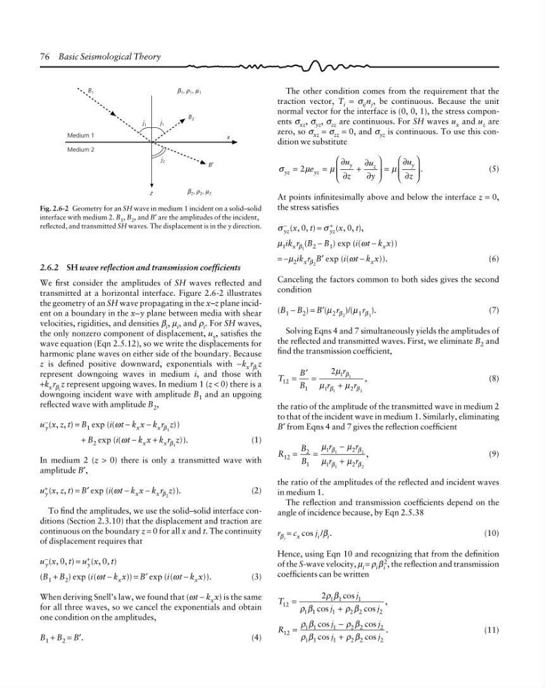
We first consider the amplitudes of SH waves reflected and
transmitted at a horizontal interface. Figure 2.6-2 illustrates
the geometry of an SH wave propagating in the x–z plane incident on a boundary in the x–y plane between media with shear
velocities, rigidities, and densities β i , µ i , and ρ i . For SH waves,
the only nonzero component of displacement, u y , satisfies the
wave equation (Eqn 2.5.12), so we write the displacements for
harmonic plane waves on either side of the boundary. Because
z is defined positive downward, exponentials with −k x r βi z
represent downgoing waves in medium i, and those with
+k x r β i z represent upgoing waves. In medium 1 (z < 0) there is a
downgoing incident wave with amplitude B 1 and an upgoing
reflected wave with amplitude B 2 ,
u −
y (x, z, t) = B 1 exp (i(ωt − k x x − k x r β 1 z))
+ B 2 exp (i(ωt − k x x + k x r β 1 z)).
(1)
In medium 2 (z > 0) there is only a transmitted wave with
amplitude B′,
u +
y (x, z, t) = B′ exp (i(ωt − k x x − k x r β 2 z)).
(2)
To find the amplitudes, we use the solid–solid interface conditions (Section 2.3.10) that the displacement and traction are
continuous on the boundary z = 0 for all x and t. The continuity
of displacement requires that
u
−
y (x, 0, t) = u
+
y (x, 0, t)
(B 1 + B 2 ) exp (i(ωt − k x x)) = B′ exp (i(ωt − k x x)).
(3)
When deriving Snell’s law, we found that (ωt − k x x) is the same
for all three waves, so we cancel the exponentials and obtain
one condition on the amplitudes,
B 1 + B 2 = B′.
(4)
Fig. 2.6-2 Geometry for an SH wave in medium 1 incident on a solid–solid
interface with medium 2. B 1 , B 2 , and B′ are the amplitudes of the incident,
reflected, and transmitted SH waves. The displacement is in the y direction.
Medium 1
B 2
Medium 2
B 1
j 1
j 1
j 2
z
B′
x
β 2 , ρ 2 , µ 2
ρ
β
µ
β 1 , ρ 1 , µ 1
ρ
β
µ
The other condition comes from the requirement that the
traction vector, T i = σ ij n j , be continuous. Because the unit
normal vector for the interface is (0, 0, 1), the stress components σ xz , σ yz , σ zz are continuous. For SH waves u x and u z are
zero, so σ xz = σ zz = 0, and σ yz is continuous. To use this condition we substitute
σ
µ
µ
µ
yz
yz
y
z
y
e
u
z
u
y
u
z
=
=
+
⎛
⎝
⎜ ⎜
⎞
⎠
⎟ ⎟
=
⎛
⎝
⎜ ⎜
⎞
⎠
⎟ ⎟
.
2
∂
∂
∂
∂
∂
∂
(5)
At points infinitesimally above and below the interface z = 0,
the stress satisfies
σ −
yz (x, 0, t) = σ +
yz (x, 0, t),
µ 1 ik x r β 1 (B 2 − B 1 ) exp (i(ωt − k x x))
= −µ 2 ik x r β 2 B′ exp (i(ωt − k x x)).
(6)
Canceling the factors common to both sides gives the second
condition
(B 1 − B 2 ) = B′(µ 2 r β 2 )/(µ 1 r β 1 ).
(7)
Solving Eqns 4 and 7 simultaneously yields the amplitudes of
the reflected and transmitted waves. First, we eliminate B 2 and
find the transmission coefficient,
T
B
B
r
r
r
12
1
1
1
2
=
=
+
,
′
2 1
1
2
µ
µ
µ
β
β
β
(8)
the ratio of the amplitude of the transmitted wave in medium 2
to that of the incident wave in medium 1. Similarly, eliminating
B′ from Eqns 4 and 7 gives the reflection coefficient
R
B
B
r
r
r
r
12
2
1
1
2
1
2
=
=
−
+
,
µ
µ
µ
µ
β
β
β
β
1
2
1
2
(9)
the ratio of the amplitudes of the reflected and incident waves
in medium 1.
The reflection and transmission coefficients depend on the
angle of incidence because, by Eqn 2.5.38
r β i = c x cos j i /β i .
(10)
Hence, using Eqn 10 and recognizing that from the definition
of the S-wave velocity, µ i = ρ i β i
2 , the reflection and transmission
coefficients can be written
T
j
j
j
12
1
1
1
1
2
2
=
+
cos
cos
cos
,
2 1
1
2
ρ β
ρ β
ρ β
R
j
j
j
j
12
1
1
2
2
1
1
2
2
=
−
+
cos
cos
cos
cos
.
ρ β
ρ β
ρ β
ρ β
1
2
1
2
(11)
2.6.2 SH wave reflection and transmission coefficients
We first consider the amplitudes of SH waves reflected and
transmitted at a horizontal interface. Figure 2.6-2 illustrates
the geometry of an SH wave propagating in the x–z plane incident on a boundary in the x–y plane between media with shear
velocities, rigidities, and densities β i , µ i , and ρ i . For SH waves,
the only nonzero component of displacement, u y , satisfies the
wave equation (Eqn 2.5.12), so we write the displacements for
harmonic plane waves on either side of the boundary. Because
z is defined positive downward, exponentials with −k x r βi z
represent downgoing waves in medium i, and those with
+k x r β i z represent upgoing waves. In medium 1 (z < 0) there is a
downgoing incident wave with amplitude B 1 and an upgoing
reflected wave with amplitude B 2 ,
u −
y (x, z, t) = B 1 exp (i(ωt − k x x − k x r β 1 z))
+ B 2 exp (i(ωt − k x x + k x r β 1 z)).
(1)
In medium 2 (z > 0) there is only a transmitted wave with
amplitude B′,
u +
y (x, z, t) = B′ exp (i(ωt − k x x − k x r β 2 z)).
(2)
To find the amplitudes, we use the solid–solid interface conditions (Section 2.3.10) that the displacement and traction are
continuous on the boundary z = 0 for all x and t. The continuity
of displacement requires that
u
−
y (x, 0, t) = u
+
y (x, 0, t)
(B 1 + B 2 ) exp (i(ωt − k x x)) = B′ exp (i(ωt − k x x)).
(3)
When deriving Snell’s law, we found that (ωt − k x x) is the same
for all three waves, so we cancel the exponentials and obtain
one condition on the amplitudes,
B 1 + B 2 = B′.
(4)
Fig. 2.6-2 Geometry for an SH wave in medium 1 incident on a solid–solid
interface with medium 2. B 1 , B 2 , and B′ are the amplitudes of the incident,
reflected, and transmitted SH waves. The displacement is in the y direction.