

74 Basic Seismological Theory
affected by diffraction. For example, we can hear around open
doorways but not see around them, because sound has a wavelength of about 0.1 m, compared to 10 −7 m for visible light.
Similarly, seismic waves that diffract around the core lose their
high-frequency components. Hence the longer the wavelength,
the poorer an approximation geometric ray theory becomes.
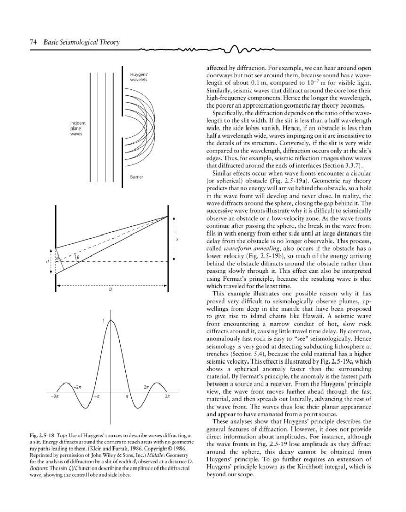
Specifically, the diffraction depends on the ratio of the wavelength to the slit width. If the slit is less than a half wavelength
wide, the side lobes vanish. Hence, if an obstacle is less than
half a wavelength wide, waves impinging on it are insensitive to
the details of its structure. Conversely, if the slit is very wide
compared to the wavelength, diffraction occurs only at the slit’s
edges. Thus, for example, seismic reflection images show waves
that diffracted around the ends of interfaces (Section 3.3.7).
Similar effects occur when wave fronts encounter a circular
(or spherical) obstacle (Fig. 2.5-19a). Geometric ray theory
predicts that no energy will arrive behind the obstacle, so a hole
in the wave front will develop and never close. In reality, the
wave diffracts around the sphere, closing the gap behind it. The
successive wave fronts illustrate why it is difficult to seismically
observe an obstacle or a low-velocity zone. As the wave fronts
continue after passing the sphere, the break in the wave front
fills in with energy from either side until at large distances the
delay from the obstacle is no longer observable. This process,
called waveform annealing, also occurs if the obstacle has a
lower velocity (Fig. 2.5-19b), so much of the energy arriving
behind the obstacle diffracts around the obstacle rather than
passing slowly through it. This effect can also be interpreted
using Fermat’s principle, because the resulting wave is that
which traveled for the least time.
This example illustrates one possible reason why it has
proved very difficult to seismologically observe plumes, upwellings from deep in the mantle that have been proposed
to give rise to island chains like Hawaii. A seismic wave
front encountering a narrow conduit of hot, slow rock
diffracts around it, causing little travel time delay. By contrast,
anomalously fast rock is easy to “see” seismologically. Hence
seismology is very good at detecting subducting lithosphere at
trenches (Section 5.4), because the cold material has a higher
seismic velocity. This effect is illustrated by Fig. 2.5-19c, which
shows a spherical anomaly faster than the surrounding
material. By Fermat’s principle, the anomaly is the fastest path
between a source and a receiver. From the Huygens’ principle
view, the wave front moves further ahead through the fast
material, and then spreads out laterally, advancing the rest of
the wave front. The waves thus lose their planar appearance
and appear to have emanated from a point source.
These analyses show that Huygens’ principle describes the
general features of diffraction. However, it does not provide
direct information about amplitudes. For instance, although
the wave fronts in Fig. 2.5-19 lose amplitude as they diffract
around the sphere, this decay cannot be obtained from
Huygens’ principle. To go further requires an extension of
Huygens’ principle known as the Kirchhoff integral, which is
beyond our scope.
Incident
plane
waves
Huygens’
wavelets
Barrier
d
θ
θ
D
x
−3π
−π
π
3π
−2π
2π
1
Fig. 2.5-18 Top: Use of Huygens’ sources to describe waves diffracting at
a slit. Energy diffracts around the corners to reach areas with no geometric
ray paths leading to them. (Klein and Furtak, 1986. Copyright © 1986.
Reprinted by permission of John Wiley & Sons, Inc.) Middle: Geometry
for the analysis of diffraction by a slit of width d, observed at a distance D.
Bottom: The (sin ζ )/ζ function describing the amplitude of the diffracted
wave, showing the central lobe and side lobes.
affected by diffraction. For example, we can hear around open
doorways but not see around them, because sound has a wavelength of about 0.1 m, compared to 10 −7 m for visible light.
Similarly, seismic waves that diffract around the core lose their
high-frequency components. Hence the longer the wavelength,
the poorer an approximation geometric ray theory becomes.
Specifically, the diffraction depends on the ratio of the wavelength to the slit width. If the slit is less than a half wavelength
wide, the side lobes vanish. Hence, if an obstacle is less than
half a wavelength wide, waves impinging on it are insensitive to
the details of its structure. Conversely, if the slit is very wide
compared to the wavelength, diffraction occurs only at the slit’s
edges. Thus, for example, seismic reflection images show waves
that diffracted around the ends of interfaces (Section 3.3.7).
Similar effects occur when wave fronts encounter a circular
(or spherical) obstacle (Fig. 2.5-19a). Geometric ray theory
predicts that no energy will arrive behind the obstacle, so a hole
in the wave front will develop and never close. In reality, the
wave diffracts around the sphere, closing the gap behind it. The
successive wave fronts illustrate why it is difficult to seismically
observe an obstacle or a low-velocity zone. As the wave fronts
continue after passing the sphere, the break in the wave front
fills in with energy from either side until at large distances the
delay from the obstacle is no longer observable. This process,
called waveform annealing, also occurs if the obstacle has a
lower velocity (Fig. 2.5-19b), so much of the energy arriving
behind the obstacle diffracts around the obstacle rather than
passing slowly through it. This effect can also be interpreted
using Fermat’s principle, because the resulting wave is that
which traveled for the least time.
This example illustrates one possible reason why it has
proved very difficult to seismologically observe plumes, upwellings from deep in the mantle that have been proposed
to give rise to island chains like Hawaii. A seismic wave
front encountering a narrow conduit of hot, slow rock
diffracts around it, causing little travel time delay. By contrast,
anomalously fast rock is easy to “see” seismologically. Hence
seismology is very good at detecting subducting lithosphere at
trenches (Section 5.4), because the cold material has a higher
seismic velocity. This effect is illustrated by Fig. 2.5-19c, which
shows a spherical anomaly faster than the surrounding
material. By Fermat’s principle, the anomaly is the fastest path
between a source and a receiver. From the Huygens’ principle
view, the wave front moves further ahead through the fast
material, and then spreads out laterally, advancing the rest of
the wave front. The waves thus lose their planar appearance
and appear to have emanated from a point source.
These analyses show that Huygens’ principle describes the
general features of diffraction. However, it does not provide
direct information about amplitudes. For instance, although
the wave fronts in Fig. 2.5-19 lose amplitude as they diffract
around the sphere, this decay cannot be obtained from
Huygens’ principle. To go further requires an extension of
Huygens’ principle known as the Kirchhoff integral, which is
beyond our scope.
Incident
plane
waves
Huygens’
wavelets
Barrier
d
θ
θ
D
x
−3π
−π
π
3π
−2π
2π
1
Fig. 2.5-18 Top: Use of Huygens’ sources to describe waves diffracting at
a slit. Energy diffracts around the corners to reach areas with no geometric
ray paths leading to them. (Klein and Furtak, 1986. Copyright © 1986.
Reprinted by permission of John Wiley & Sons, Inc.) Middle: Geometry
for the analysis of diffraction by a slit of width d, observed at a distance D.
Bottom: The (sin ζ )/ζ function describing the amplitude of the diffracted
wave, showing the central lobe and side lobes.