

2.5 Snell’s law 73
Incident
wave
Reflected
wave
Transmitted
wave
Medium 1
Medium 2
A
D
B
C
O
C′
A′
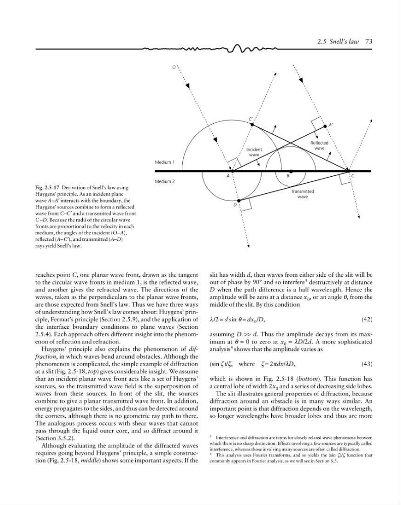
Fig. 2.5-17 Derivation of Snell’s law using
Huygens’ principle. As an incident plane
wave A–A′ interacts with the boundary, the
Huygens’ sources combine to form a reflected
wave front C–C′ and a transmitted wave front
C –D. Because the radii of the circular wave
fronts are proportional to the velocity in each
medium, the angles of the incident (O–A),
reflected (A–C′), and transmitted (A–D)
rays yield Snell’s law.
3 Interference and diffraction are terms for closely related wave phenomena between
which there is no sharp distinction. Effects involving a few sources are typically called
interference, whereas those involving many sources are often called diffraction.
4 This analysis uses Fourier transforms, and so yields the (sin ζ)/ζ function that
commonly appears in Fourier analysis, as we will see in Section 6.3.
reaches point C, one planar wave front, drawn as the tangent
to the circular wave fronts in medium 1, is the reflected wave,
and another gives the refracted wave. The directions of the
waves, taken as the perpendiculars to the planar wave fronts,
are those expected from Snell’s law. Thus we have three ways
of understanding how Snell’s law comes about: Huygens’ principle, Fermat’s principle (Section 2.5.9), and the application of
the interface boundary conditions to plane waves (Section
2.5.4). Each approach offers different insight into the phenomenon of reflection and refraction.
Huygens’ principle also explains the phenomenon of diffraction, in which waves bend around obstacles. Although the
phenomenon is complicated, the simple example of diffraction
at a slit (Fig. 2.5-18, top) gives considerable insight. We assume
that an incident planar wave front acts like a set of Huygens’
sources, so the transmitted wave field is the superposition of
waves from these sources. In front of the slit, the sources
combine to give a planar transmitted wave front. In addition,
energy propagates to the sides, and thus can be detected around
the corners, although there is no geometric ray path to there.
The analogous process occurs with shear waves that cannot
pass through the liquid outer core, and so diffract around it
(Section 3.5.2).
Although evaluating the amplitude of the diffracted waves
requires going beyond Huygens’ principle, a simple construction (Fig. 2.5-18, middle) shows some important aspects. If the
slit has width d, then waves from either side of the slit will be
out of phase by 90° and so interfere 3 destructively at distance
D when the path difference is a half wavelength. Hence the
amplitude will be zero at a distance x 0 , or an angle θ, from the
middle of the slit. By this condition
λ/2 = d sin θ ≈ dx 0 /D,
(42)
assuming D >> d. Thus the amplitude decays from its maximum at θ = 0 to zero at x 0 = λD/2d. A more sophisticated
analysis 4 shows that the amplitude varies as
(sin ζ)/ζ, where ζ = 2πdx/λD,
(43)
which is shown in Fig. 2.5-18 (bottom). This function has
a central lobe of width 2x 0 and a series of decreasing side lobes.
The slit illustrates general properties of diffraction, because
diffraction around an obstacle is in many ways similar. An
important point is that diffraction depends on the wavelength,
so longer wavelengths have broader lobes and thus are more
Incident
wave
Reflected
wave
Transmitted
wave
Medium 1
Medium 2
A
D
B
C
O
C′
A′
Fig. 2.5-17 Derivation of Snell’s law using
Huygens’ principle. As an incident plane
wave A–A′ interacts with the boundary, the
Huygens’ sources combine to form a reflected
wave front C–C′ and a transmitted wave front
C –D. Because the radii of the circular wave
fronts are proportional to the velocity in each
medium, the angles of the incident (O–A),
reflected (A–C′), and transmitted (A–D)
rays yield Snell’s law.
3 Interference and diffraction are terms for closely related wave phenomena between
which there is no sharp distinction. Effects involving a few sources are typically called
interference, whereas those involving many sources are often called diffraction.
4 This analysis uses Fourier transforms, and so yields the (sin ζ)/ζ function that
commonly appears in Fourier analysis, as we will see in Section 6.3.
reaches point C, one planar wave front, drawn as the tangent
to the circular wave fronts in medium 1, is the reflected wave,
and another gives the refracted wave. The directions of the
waves, taken as the perpendiculars to the planar wave fronts,
are those expected from Snell’s law. Thus we have three ways
of understanding how Snell’s law comes about: Huygens’ principle, Fermat’s principle (Section 2.5.9), and the application of
the interface boundary conditions to plane waves (Section
2.5.4). Each approach offers different insight into the phenomenon of reflection and refraction.
Huygens’ principle also explains the phenomenon of diffraction, in which waves bend around obstacles. Although the
phenomenon is complicated, the simple example of diffraction
at a slit (Fig. 2.5-18, top) gives considerable insight. We assume
that an incident planar wave front acts like a set of Huygens’
sources, so the transmitted wave field is the superposition of
waves from these sources. In front of the slit, the sources
combine to give a planar transmitted wave front. In addition,
energy propagates to the sides, and thus can be detected around
the corners, although there is no geometric ray path to there.
The analogous process occurs with shear waves that cannot
pass through the liquid outer core, and so diffract around it
(Section 3.5.2).
Although evaluating the amplitude of the diffracted waves
requires going beyond Huygens’ principle, a simple construction (Fig. 2.5-18, middle) shows some important aspects. If the
slit has width d, then waves from either side of the slit will be
out of phase by 90° and so interfere 3 destructively at distance
D when the path difference is a half wavelength. Hence the
amplitude will be zero at a distance x 0 , or an angle θ, from the
middle of the slit. By this condition
λ/2 = d sin θ ≈ dx 0 /D,
(42)
assuming D >> d. Thus the amplitude decays from its maximum at θ = 0 to zero at x 0 = λD/2d. A more sophisticated
analysis 4 shows that the amplitude varies as
(sin ζ)/ζ, where ζ = 2πdx/λD,
(43)
which is shown in Fig. 2.5-18 (bottom). This function has
a central lobe of width 2x 0 and a series of decreasing side lobes.
The slit illustrates general properties of diffraction, because
diffraction around an obstacle is in many ways similar. An
important point is that diffraction depends on the wavelength,
so longer wavelengths have broader lobes and thus are more