

72 Basic Seismological Theory
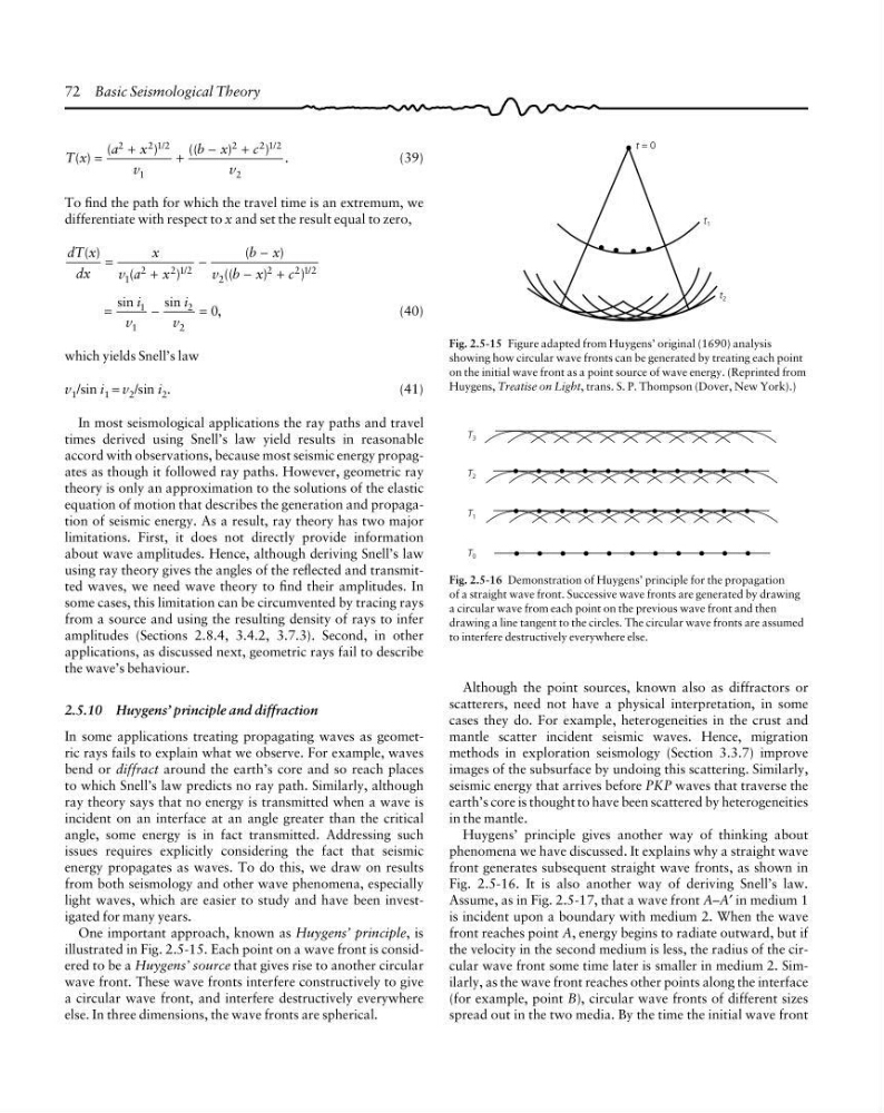
Fig. 2.5-15 Figure adapted from Huygens’ original (1690) analysis
showing how circular wave fronts can be generated by treating each point
on the initial wave front as a point source of wave energy. (Reprinted from
Huygens, Treatise on Light, trans. S. P. Thompson (Dover, New York).)
t = 0
t 1
t 2
T x
a
x
v
b x
c
v
( )
(
)
((
)
) .
/
/
=
+
+
−
+
2
212
1
2
212
2
(39)
To find the path for which the travel time is an extremum, we
differentiate with respect to x and set the result equal to zero,
dT x
dx
x
v a
x
b x
v b x
c
( )
(
)
(
)
((
)
)
/
/
=
+
−
−
−
+
1
2
212
2
2
212
i
v
i
v
sin
sin
,
=
−
=
1
1
2
2
0
(40)
which yields Snell’s law
v 1 /sin i 1 = v 2 /sin i 2 .
(41)
In most seismological applications the ray paths and travel
times derived using Snell’s law yield results in reasonable
accord with observations, because most seismic energy propagates as though it followed ray paths. However, geometric ray
theory is only an approximation to the solutions of the elastic
equation of motion that describes the generation and propagation of seismic energy. As a result, ray theory has two major
limitations. First, it does not directly provide information
about wave amplitudes. Hence, although deriving Snell’s law
using ray theory gives the angles of the reflected and transmitted waves, we need wave theory to find their amplitudes. In
some cases, this limitation can be circumvented by tracing rays
from a source and using the resulting density of rays to infer
amplitudes (Sections 2.8.4, 3.4.2, 3.7.3). Second, in other
applications, as discussed next, geometric rays fail to describe
the wave’s behaviour.
2.5.10 Huygens’ principle and diffraction
In some applications treating propagating waves as geometric rays fails to explain what we observe. For example, waves
bend or diffract around the earth’s core and so reach places
to which Snell’s law predicts no ray path. Similarly, although
ray theory says that no energy is transmitted when a wave is
incident on an interface at an angle greater than the critical
angle, some energy is in fact transmitted. Addressing such
issues requires explicitly considering the fact that seismic
energy propagates as waves. To do this, we draw on results
from both seismology and other wave phenomena, especially
light waves, which are easier to study and have been investigated for many years.
One important approach, known as Huygens’ principle, is
illustrated in Fig. 2.5-15. Each point on a wave front is considered to be a Huygens’ source that gives rise to another circular
wave front. These wave fronts interfere constructively to give
a circular wave front, and interfere destructively everywhere
else. In three dimensions, the wave fronts are spherical.
Fig. 2.5-16 Demonstration of Huygens’ principle for the propagation
of a straight wave front. Successive wave fronts are generated by drawing
a circular wave from each point on the previous wave front and then
drawing a line tangent to the circles. The circular wave fronts are assumed
to interfere destructively everywhere else.
T 3
T 2
T 1
T 0
Although the point sources, known also as diffractors or
scatterers, need not have a physical interpretation, in some
cases they do. For example, heterogeneities in the crust and
mantle scatter incident seismic waves. Hence, migration
methods in exploration seismology (Section 3.3.7) improve
images of the subsurface by undoing this scattering. Similarly,
seismic energy that arrives before PKP waves that traverse the
earth’s core is thought to have been scattered by heterogeneities
in the mantle.
Huygens’ principle gives another way of thinking about
phenomena we have discussed. It explains why a straight wave
front generates subsequent straight wave fronts, as shown in
Fig. 2.5-16. It is also another way of deriving Snell’s law.
Assume, as in Fig. 2.5-17, that a wave front A–A′ in medium 1
is incident upon a boundary with medium 2. When the wave
front reaches point A, energy begins to radiate outward, but if
the velocity in the second medium is less, the radius of the circular wave front some time later is smaller in medium 2. Similarly, as the wave front reaches other points along the interface
(for example, point B), circular wave fronts of different sizes
spread out in the two media. By the time the initial wave front
Fig. 2.5-15 Figure adapted from Huygens’ original (1690) analysis
showing how circular wave fronts can be generated by treating each point
on the initial wave front as a point source of wave energy. (Reprinted from
Huygens, Treatise on Light, trans. S. P. Thompson (Dover, New York).)
t = 0
t 1
t 2
T x
a
x
v
b x
c
v
( )
(
)
((
)
) .
/
/
=
+
+
−
+
2
212
1
2
212
2
(39)
To find the path for which the travel time is an extremum, we
differentiate with respect to x and set the result equal to zero,
dT x
dx
x
v a
x
b x
v b x
c
( )
(
)
(
)
((
)
)
/
/
=
+
−
−
−
+
1
2
212
2
2
212
i
v
i
v
sin
sin
,
=
−
=
1
1
2
2
0
(40)
which yields Snell’s law
v 1 /sin i 1 = v 2 /sin i 2 .
(41)
In most seismological applications the ray paths and travel
times derived using Snell’s law yield results in reasonable
accord with observations, because most seismic energy propagates as though it followed ray paths. However, geometric ray
theory is only an approximation to the solutions of the elastic
equation of motion that describes the generation and propagation of seismic energy. As a result, ray theory has two major
limitations. First, it does not directly provide information
about wave amplitudes. Hence, although deriving Snell’s law
using ray theory gives the angles of the reflected and transmitted waves, we need wave theory to find their amplitudes. In
some cases, this limitation can be circumvented by tracing rays
from a source and using the resulting density of rays to infer
amplitudes (Sections 2.8.4, 3.4.2, 3.7.3). Second, in other
applications, as discussed next, geometric rays fail to describe
the wave’s behaviour.
2.5.10 Huygens’ principle and diffraction
In some applications treating propagating waves as geometric rays fails to explain what we observe. For example, waves
bend or diffract around the earth’s core and so reach places
to which Snell’s law predicts no ray path. Similarly, although
ray theory says that no energy is transmitted when a wave is
incident on an interface at an angle greater than the critical
angle, some energy is in fact transmitted. Addressing such
issues requires explicitly considering the fact that seismic
energy propagates as waves. To do this, we draw on results
from both seismology and other wave phenomena, especially
light waves, which are easier to study and have been investigated for many years.
One important approach, known as Huygens’ principle, is
illustrated in Fig. 2.5-15. Each point on a wave front is considered to be a Huygens’ source that gives rise to another circular
wave front. These wave fronts interfere constructively to give
a circular wave front, and interfere destructively everywhere
else. In three dimensions, the wave fronts are spherical.
Fig. 2.5-16 Demonstration of Huygens’ principle for the propagation
of a straight wave front. Successive wave fronts are generated by drawing
a circular wave from each point on the previous wave front and then
drawing a line tangent to the circles. The circular wave fronts are assumed
to interfere destructively everywhere else.
T 3
T 2
T 1
T 0
Although the point sources, known also as diffractors or
scatterers, need not have a physical interpretation, in some
cases they do. For example, heterogeneities in the crust and
mantle scatter incident seismic waves. Hence, migration
methods in exploration seismology (Section 3.3.7) improve
images of the subsurface by undoing this scattering. Similarly,
seismic energy that arrives before PKP waves that traverse the
earth’s core is thought to have been scattered by heterogeneities
in the mantle.
Huygens’ principle gives another way of thinking about
phenomena we have discussed. It explains why a straight wave
front generates subsequent straight wave fronts, as shown in
Fig. 2.5-16. It is also another way of deriving Snell’s law.
Assume, as in Fig. 2.5-17, that a wave front A–A′ in medium 1
is incident upon a boundary with medium 2. When the wave
front reaches point A, energy begins to radiate outward, but if
the velocity in the second medium is less, the radius of the circular wave front some time later is smaller in medium 2. Similarly, as the wave front reaches other points along the interface
(for example, point B), circular wave fronts of different sizes
spread out in the two media. By the time the initial wave front