

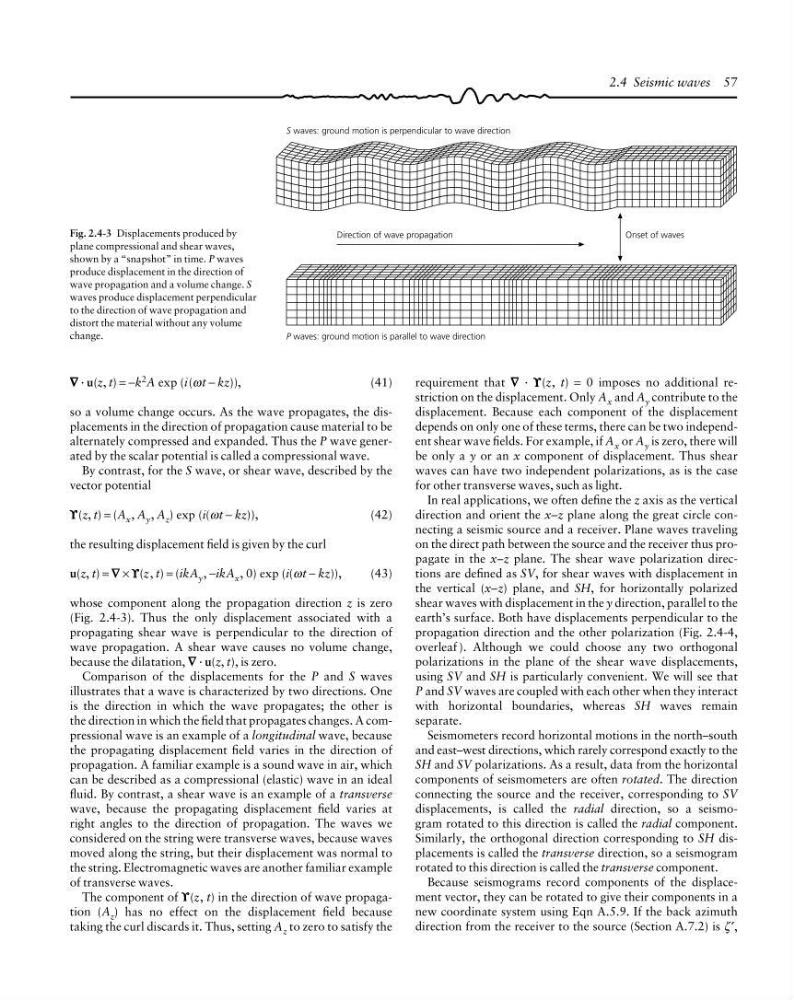
S waves: ground motion is perpendicular to wave direction
Direction of wave propagation
Onset of waves
P waves: ground motion is parallel to wave direction
2.4 Seismic waves 57
∇
∇ ∇
∇ ∇ · u(z, t) = −k
2
A exp (i(ωt − kz)),
(41)
so a volume change occurs. As the wave propagates, the displacements in the direction of propagation cause material to be
alternately compressed and expanded. Thus the P wave generated by the scalar potential is called a compressional wave.
By contrast, for the S wave, or shear wave, described by the
vector potential
ϒ
ϒ ϒ
ϒ ϒ(z, t) = (A x , A y , A z ) exp (i(ωt − kz)),
(42)
the resulting displacement field is given by the curl
u(z, t) = ∇
∇ ∇
∇ ∇ × ϒ
ϒ ϒ
ϒ ϒ(z, t) = (ikA y , −ikA x , 0) exp (i(ωt − kz)),
(43)
whose component along the propagation direction z is zero
(Fig. 2.4-3). Thus the only displacement associated with a
propagating shear wave is perpendicular to the direction of
wave propagation. A shear wave causes no volume change,
because the dilatation, ∇
∇ ∇
∇ ∇ · u(z, t), is zero.
Comparison of the displacements for the P and S waves
illustrates that a wave is characterized by two directions. One
is the direction in which the wave propagates; the other is
the direction in which the field that propagates changes. A compressional wave is an example of a longitudinal wave, because
the propagating displacement field varies in the direction of
propagation. A familiar example is a sound wave in air, which
can be described as a compressional (elastic) wave in an ideal
fluid. By contrast, a shear wave is an example of a transverse
wave, because the propagating displacement field varies at
right angles to the direction of propagation. The waves we
considered on the string were transverse waves, because waves
moved along the string, but their displacement was normal to
the string. Electromagnetic waves are another familiar example
of transverse waves.
The component of ϒ
ϒ ϒ
ϒ ϒ(z, t) in the direction of wave propagation (A z ) has no effect on the displacement field because
taking the curl discards it. Thus, setting A z to zero to satisfy the
requirement that ∇
∇ ∇
∇ ∇ · ϒ
ϒ ϒ
ϒ ϒ(z, t) = 0 imposes no additional restriction on the displacement. Only A x and A y contribute to the
displacement. Because each component of the displacement
depends on only one of these terms, there can be two independent shear wave fields. For example, if A x or A y is zero, there will
be only a y or an x component of displacement. Thus shear
waves can have two independent polarizations, as is the case
for other transverse waves, such as light.
In real applications, we often define the z axis as the vertical
direction and orient the x–z plane along the great circle connecting a seismic source and a receiver. Plane waves traveling
on the direct path between the source and the receiver thus propagate in the x–z plane. The shear wave polarization directions are defined as SV, for shear waves with displacement in
the vertical (x–z) plane, and SH, for horizontally polarized
shear waves with displacement in the y direction, parallel to the
earth’s surface. Both have displacements perpendicular to the
propagation direction and the other polarization (Fig. 2.4-4,
overleaf ). Although we could choose any two orthogonal
polarizations in the plane of the shear wave displacements,
using SV and SH is particularly convenient. We will see that
P and SV waves are coupled with each other when they interact
with horizontal boundaries, whereas SH waves remain
separate.
Seismometers record horizontal motions in the north–south
and east–west directions, which rarely correspond exactly to the
SH and SV polarizations. As a result, data from the horizontal
components of seismometers are often rotated. The direction
connecting the source and the receiver, corresponding to SV
displacements, is called the radial direction, so a seismogram rotated to this direction is called the radial component.
Similarly, the orthogonal direction corresponding to SH displacements is called the transverse direction, so a seismogram
rotated to this direction is called the transverse component.
Because seismograms record components of the displacement vector, they can be rotated to give their components in a
new coordinate system using Eqn A.5.9. If the back azimuth
direction from the receiver to the source (Section A.7.2) is ζ ′,
Fig. 2.4-3 Displacements produced by
plane compressional and shear waves,
shown by a “snapshot” in time. P waves
produce displacement in the direction of
wave propagation and a volume change. S
waves produce displacement perpendicular
to the direction of wave propagation and
distort the material without any volume
change.
Direction of wave propagation
Onset of waves
P waves: ground motion is parallel to wave direction
2.4 Seismic waves 57
∇
∇ ∇
∇ ∇ · u(z, t) = −k
2
A exp (i(ωt − kz)),
(41)
so a volume change occurs. As the wave propagates, the displacements in the direction of propagation cause material to be
alternately compressed and expanded. Thus the P wave generated by the scalar potential is called a compressional wave.
By contrast, for the S wave, or shear wave, described by the
vector potential
ϒ
ϒ ϒ
ϒ ϒ(z, t) = (A x , A y , A z ) exp (i(ωt − kz)),
(42)
the resulting displacement field is given by the curl
u(z, t) = ∇
∇ ∇
∇ ∇ × ϒ
ϒ ϒ
ϒ ϒ(z, t) = (ikA y , −ikA x , 0) exp (i(ωt − kz)),
(43)
whose component along the propagation direction z is zero
(Fig. 2.4-3). Thus the only displacement associated with a
propagating shear wave is perpendicular to the direction of
wave propagation. A shear wave causes no volume change,
because the dilatation, ∇
∇ ∇
∇ ∇ · u(z, t), is zero.
Comparison of the displacements for the P and S waves
illustrates that a wave is characterized by two directions. One
is the direction in which the wave propagates; the other is
the direction in which the field that propagates changes. A compressional wave is an example of a longitudinal wave, because
the propagating displacement field varies in the direction of
propagation. A familiar example is a sound wave in air, which
can be described as a compressional (elastic) wave in an ideal
fluid. By contrast, a shear wave is an example of a transverse
wave, because the propagating displacement field varies at
right angles to the direction of propagation. The waves we
considered on the string were transverse waves, because waves
moved along the string, but their displacement was normal to
the string. Electromagnetic waves are another familiar example
of transverse waves.
The component of ϒ
ϒ ϒ
ϒ ϒ(z, t) in the direction of wave propagation (A z ) has no effect on the displacement field because
taking the curl discards it. Thus, setting A z to zero to satisfy the
requirement that ∇
∇ ∇
∇ ∇ · ϒ
ϒ ϒ
ϒ ϒ(z, t) = 0 imposes no additional restriction on the displacement. Only A x and A y contribute to the
displacement. Because each component of the displacement
depends on only one of these terms, there can be two independent shear wave fields. For example, if A x or A y is zero, there will
be only a y or an x component of displacement. Thus shear
waves can have two independent polarizations, as is the case
for other transverse waves, such as light.
In real applications, we often define the z axis as the vertical
direction and orient the x–z plane along the great circle connecting a seismic source and a receiver. Plane waves traveling
on the direct path between the source and the receiver thus propagate in the x–z plane. The shear wave polarization directions are defined as SV, for shear waves with displacement in
the vertical (x–z) plane, and SH, for horizontally polarized
shear waves with displacement in the y direction, parallel to the
earth’s surface. Both have displacements perpendicular to the
propagation direction and the other polarization (Fig. 2.4-4,
overleaf ). Although we could choose any two orthogonal
polarizations in the plane of the shear wave displacements,
using SV and SH is particularly convenient. We will see that
P and SV waves are coupled with each other when they interact
with horizontal boundaries, whereas SH waves remain
separate.
Seismometers record horizontal motions in the north–south
and east–west directions, which rarely correspond exactly to the
SH and SV polarizations. As a result, data from the horizontal
components of seismometers are often rotated. The direction
connecting the source and the receiver, corresponding to SV
displacements, is called the radial direction, so a seismogram rotated to this direction is called the radial component.
Similarly, the orthogonal direction corresponding to SH displacements is called the transverse direction, so a seismogram
rotated to this direction is called the transverse component.
Because seismograms record components of the displacement vector, they can be rotated to give their components in a
new coordinate system using Eqn A.5.9. If the back azimuth
direction from the receiver to the source (Section A.7.2) is ζ ′,
Fig. 2.4-3 Displacements produced by
plane compressional and shear waves,
shown by a “snapshot” in time. P waves
produce displacement in the direction of
wave propagation and a volume change. S
waves produce displacement perpendicular
to the direction of wave propagation and
distort the material without any volume
change.