

464 Appendix
Earthquake
Earthquake
Great
circle
path
Station
Great
circle path
N
x 2
x 1
x 3
x S
∆
b
x E
e φ
e θ
e θ
b
e φ
ζ
ζ
90° − ζ
ˆ
ˆ
ˆ
ˆ
ˆ
ˆ
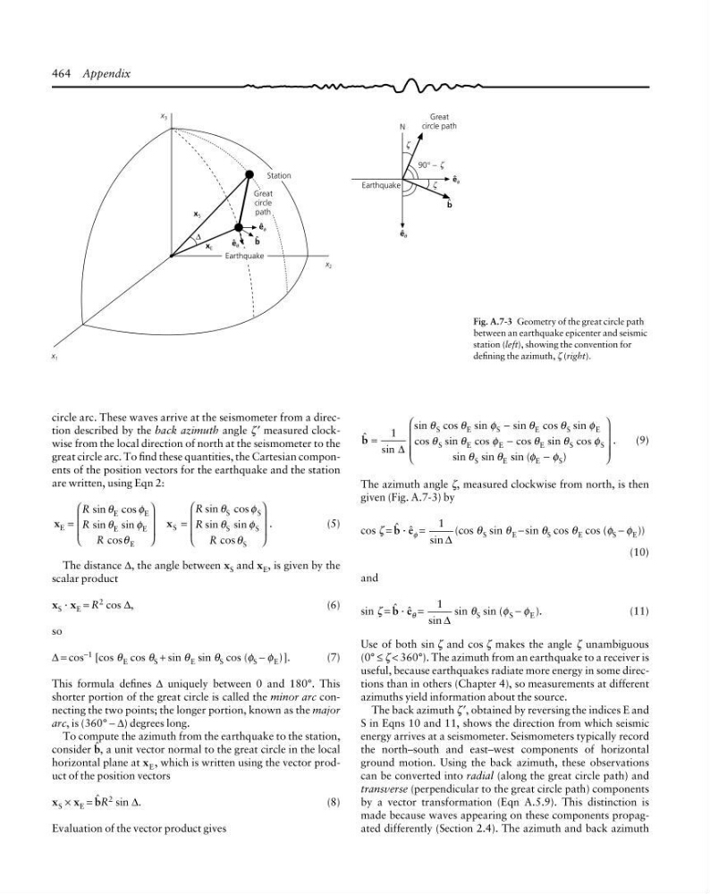
Fig. A.7-3 Geometry of the great circle path
between an earthquake epicenter and seismic
station (left), showing the convention for
defining the azimuth, ζ (right).
circle arc. These waves arrive at the seismometer from a direction described by the back azimuth angle ζ ′ measured clockwise from the local direction of north at the seismometer to the
great circle arc. To find these quantities, the Cartesian components of the position vectors for the earthquake and the station
are written, using Eqn 2:
x
x
E
E
E
E
E
E
S
S
S
S
S
S
=
⎛
⎝
⎜
⎜
⎞
⎠
⎟
⎟
=
⎛
⎝
⎜
⎜
⎞
⎠
⎟
⎟
sin cos
sin sin
cos
sin cos
sin sin
cos
.
R
R
R
R
R
R
θ
φ
θ
φ
θ
θ
φ
θ
φ
θ
(5)
The distance ∆, the angle between x S and x E , is given by the
scalar product
x S · x E = R 2 cos ∆,
(6)
so
∆ = cos −1 [cos θ E cos θ S + sin θ E sin θ S cos (φ S − φ E )].
(7)
This formula defines ∆ uniquely between 0 and 180°. This
shorter portion of the great circle is called the minor arc connecting the two points; the longer portion, known as the major
arc, is (360° − ∆) degrees long.
To compute the azimuth from the earthquake to the station,
consider 1, a unit vector normal to the great circle in the local
horizontal plane at x E , which is written using the vector product of the position vectors
x S × x E = 1R 2 sin ∆.
(8)
Evaluation of the vector product gives
1
sin
sin cos sin
sin
cos sin
cos sin
cos
cos sin cos
sin sin sin (
)
.
=
−
−
−
⎛
⎝
⎜
⎜
⎜
⎞
⎠
⎟
⎟
⎟
1
∆
θ
θ
φ
θ
θ
φ
θ
θ
φ
θ
θ
φ
θ
θ
φ
φ
S
E
S
E
S
E
S
E
E
E
S
S
S
E
E
S
(9)
The azimuth angle ζ, measured clockwise from north, is then
given (Fig. A.7-3) by
cos ζ = 1 · ê φ =
1
sin ∆
(cos θ S sin θ E − sin θ S cos θ E cos (φ S − φ E ))
(10)
and
sin ζ = 1 · ê θ =
1
sin ∆
sin θ S sin (φ S − φ E ).
(11)
Use of both sin ζ and cos ζ makes the angle ζ unambiguous
(0° ≤ ζ < 360°). The azimuth from an earthquake to a receiver is
useful, because earthquakes radiate more energy in some directions than in others (Chapter 4), so measurements at different
azimuths yield information about the source.
The back azimuth ζ ′, obtained by reversing the indices E and
S in Eqns 10 and 11, shows the direction from which seismic
energy arrives at a seismometer. Seismometers typically record
the north–south and east–west components of horizontal
ground motion. Using the back azimuth, these observations
can be converted into radial (along the great circle path) and
transverse (perpendicular to the great circle path) components
by a vector transformation (Eqn A.5.9). This distinction is
made because waves appearing on these components propagated differently (Section 2.4). The azimuth and back azimuth
Earthquake
Earthquake
Great
circle
path
Station
Great
circle path
N
x 2
x 1
x 3
x S
∆
b
x E
e φ
e θ
e θ
b
e φ
ζ
ζ
90° − ζ
ˆ
ˆ
ˆ
ˆ
ˆ
ˆ
Fig. A.7-3 Geometry of the great circle path
between an earthquake epicenter and seismic
station (left), showing the convention for
defining the azimuth, ζ (right).
circle arc. These waves arrive at the seismometer from a direction described by the back azimuth angle ζ ′ measured clockwise from the local direction of north at the seismometer to the
great circle arc. To find these quantities, the Cartesian components of the position vectors for the earthquake and the station
are written, using Eqn 2:
x
x
E
E
E
E
E
E
S
S
S
S
S
S
=
⎛
⎝
⎜
⎜
⎞
⎠
⎟
⎟
=
⎛
⎝
⎜
⎜
⎞
⎠
⎟
⎟
sin cos
sin sin
cos
sin cos
sin sin
cos
.
R
R
R
R
R
R
θ
φ
θ
φ
θ
θ
φ
θ
φ
θ
(5)
The distance ∆, the angle between x S and x E , is given by the
scalar product
x S · x E = R 2 cos ∆,
(6)
so
∆ = cos −1 [cos θ E cos θ S + sin θ E sin θ S cos (φ S − φ E )].
(7)
This formula defines ∆ uniquely between 0 and 180°. This
shorter portion of the great circle is called the minor arc connecting the two points; the longer portion, known as the major
arc, is (360° − ∆) degrees long.
To compute the azimuth from the earthquake to the station,
consider 1, a unit vector normal to the great circle in the local
horizontal plane at x E , which is written using the vector product of the position vectors
x S × x E = 1R 2 sin ∆.
(8)
Evaluation of the vector product gives
1
sin
sin cos sin
sin
cos sin
cos sin
cos
cos sin cos
sin sin sin (
)
.
=
−
−
−
⎛
⎝
⎜
⎜
⎜
⎞
⎠
⎟
⎟
⎟
1
∆
θ
θ
φ
θ
θ
φ
θ
θ
φ
θ
θ
φ
θ
θ
φ
φ
S
E
S
E
S
E
S
E
E
E
S
S
S
E
E
S
(9)
The azimuth angle ζ, measured clockwise from north, is then
given (Fig. A.7-3) by
cos ζ = 1 · ê φ =
1
sin ∆
(cos θ S sin θ E − sin θ S cos θ E cos (φ S − φ E ))
(10)
and
sin ζ = 1 · ê θ =
1
sin ∆
sin θ S sin (φ S − φ E ).
(11)
Use of both sin ζ and cos ζ makes the angle ζ unambiguous
(0° ≤ ζ < 360°). The azimuth from an earthquake to a receiver is
useful, because earthquakes radiate more energy in some directions than in others (Chapter 4), so measurements at different
azimuths yield information about the source.
The back azimuth ζ ′, obtained by reversing the indices E and
S in Eqns 10 and 11, shows the direction from which seismic
energy arrives at a seismometer. Seismometers typically record
the north–south and east–west components of horizontal
ground motion. Using the back azimuth, these observations
can be converted into radial (along the great circle path) and
transverse (perpendicular to the great circle path) components
by a vector transformation (Eqn A.5.9). This distinction is
made because waves appearing on these components propagated differently (Section 2.4). The azimuth and back azimuth