

456 Appendix
u 2 = ê 2 · u′ = a 12 u′ 1 + a 22 u′ 2 + a 32 u′ 3 ,
u 3 = ê 3 · u′ = a 13 u′ 1 + a 23 u′ 2 + a 33 u′ 3 .
(10)
Combining these to express the reverse transformation in
vector–matrix form,
u
u
u
a
a
a
a
a
a
a
a
a
u
u
u
1
2
3
11
21
31
12
22
32
13
23
33
1
2
3
⎛
⎝
⎜
⎜
⎜
⎞
⎠
⎟
⎟
⎟
=
⎛
⎝
⎜
⎜
⎜
⎞
⎠
⎟
⎟
⎟
⎛
⎝
⎜
⎜
⎜
⎞
⎠
⎟
⎟
⎟
,
′
′
′
(11)
shows that the reverse transformation matrix is just the transpose of the transformation matrix A
u = A T u′.
(12)
Hence a unit basis vector in the primed system
ê′ 1 = 1ê′ 1 + 0ê′ 2 + 0ê′ 3
(13)
becomes, by the matrix transformation,
a 11 ê 1 + a 12 ê 2 + a 13 ê 3
(14)
in the unprimed system. This is the first row of A, so the rows of
A are the primed basis vectors expressed in the unprimed coordinates. This is natural because the transformations are related
by the matrix transpose.
Alternatively, the reverse transformation can be found
directly by starting with u′ = Au and multiplying both sides by
the inverse matrix
A −1 u′ = A −1 Au = Iu = u.
(15)
Comparison with Eqn 12 shows that the inverse of the transformation matrix equals its transpose, so the transformation
matrix is an orthogonal matrix. This seems reasonable because
the columns of A, which represent orthogonal basis vectors,
are orthogonal. Similarly, the rows of A are orthogonal. As a
result, such coordinate transformations are called orthogonal
transformations. An important feature of orthogonal transformations, whose proof is left as a homework problem, is that
they preserve the length of vectors.
The transformation relations, Eqns 4 and 12, provide a
mathematical definition of a vector. Any vector must transform
between coordinate systems in this way. A set of three entities
defined at points in space (for example, temperature, pressure,
and density) that does not obey the transformation equations is
not a vector.
A.5.2 Eigenvalues and eigenvectors
The product of an arbitrary n × n matrix A and an arbitrary
n-component vector x
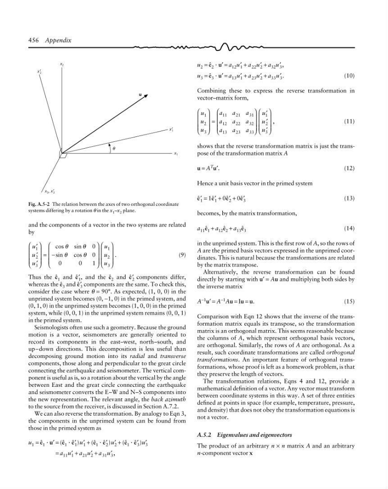
Fig. A.5-2 The relation between the axes of two orthogonal coordinate
systems differing by a rotation θ in the x 1 –x 2 plane.
x 1
x′ 1
x 2
x′ 2
x 3 , x′ 3
u
θ
and the components of a vector in the two systems are related
by
u
u
u
u
u
u
1
2
3
1
2
3
0
0
0
0
1
′
′
′
⎛
⎝
⎜
⎜
⎜
⎞
⎠
⎟
⎟
⎟
= −
⎛
⎝
⎜
⎜
⎜
⎞
⎠
⎟
⎟
⎟
⎛
⎝
⎜
⎜
⎜
⎞
⎠
⎟
⎟
⎟
cos
sin
sin
cos
.
θ
θ
θ
θ
(9)
Thus the ê 1 and ê′ 1 , and the ê 2 and ê′ 2 components differ,
whereas the ê 3 and ê′ 3 components are the same. To check this,
consider the case where θ = 90°. As expected, (1, 0, 0) in the
unprimed system becomes (0, −1, 0) in the primed system, and
(0, 1, 0) in the unprimed system becomes (1, 0, 0) in the primed
system, while (0, 0, 1) in the unprimed system remains (0, 0, 1)
in the primed system.
Seismologists often use such a geometry. Because the ground
motion is a vector, seismometers are generally oriented to
record its components in the east–west, north–south, and
up–down directions. This decomposition is less useful than
decomposing ground motion into its radial and transverse
components, those along and perpendicular to the great circle
connecting the earthquake and seismometer. The vertical component is useful as is, so a rotation about the vertical by the angle
between East and the great circle connecting the earthquake
and seismometer converts the E–W and N–S components into
the new representation. The relevant angle, the back azimuth
to the source from the receiver, is discussed in Section A.7.2.
We can also reverse the transformation. By analogy to Eqn 3,
the components in the unprimed system can be found from
those in the primed system as
u 1 = ê 1 · u′ = (ê 1 · ê′ 1 )u′ 1 + (ê 1 · ê′ 2 )u′ 2 + (ê 1 · ê′ 3 )u′ 3
= a 11 u′ 1 + a 21 u′ 2 + a 31 u′ 3 ,
u 2 = ê 2 · u′ = a 12 u′ 1 + a 22 u′ 2 + a 32 u′ 3 ,
u 3 = ê 3 · u′ = a 13 u′ 1 + a 23 u′ 2 + a 33 u′ 3 .
(10)
Combining these to express the reverse transformation in
vector–matrix form,
u
u
u
a
a
a
a
a
a
a
a
a
u
u
u
1
2
3
11
21
31
12
22
32
13
23
33
1
2
3
⎛
⎝
⎜
⎜
⎜
⎞
⎠
⎟
⎟
⎟
=
⎛
⎝
⎜
⎜
⎜
⎞
⎠
⎟
⎟
⎟
⎛
⎝
⎜
⎜
⎜
⎞
⎠
⎟
⎟
⎟
,
′
′
′
(11)
shows that the reverse transformation matrix is just the transpose of the transformation matrix A
u = A T u′.
(12)
Hence a unit basis vector in the primed system
ê′ 1 = 1ê′ 1 + 0ê′ 2 + 0ê′ 3
(13)
becomes, by the matrix transformation,
a 11 ê 1 + a 12 ê 2 + a 13 ê 3
(14)
in the unprimed system. This is the first row of A, so the rows of
A are the primed basis vectors expressed in the unprimed coordinates. This is natural because the transformations are related
by the matrix transpose.
Alternatively, the reverse transformation can be found
directly by starting with u′ = Au and multiplying both sides by
the inverse matrix
A −1 u′ = A −1 Au = Iu = u.
(15)
Comparison with Eqn 12 shows that the inverse of the transformation matrix equals its transpose, so the transformation
matrix is an orthogonal matrix. This seems reasonable because
the columns of A, which represent orthogonal basis vectors,
are orthogonal. Similarly, the rows of A are orthogonal. As a
result, such coordinate transformations are called orthogonal
transformations. An important feature of orthogonal transformations, whose proof is left as a homework problem, is that
they preserve the length of vectors.
The transformation relations, Eqns 4 and 12, provide a
mathematical definition of a vector. Any vector must transform
between coordinate systems in this way. A set of three entities
defined at points in space (for example, temperature, pressure,
and density) that does not obey the transformation equations is
not a vector.
A.5.2 Eigenvalues and eigenvectors
The product of an arbitrary n × n matrix A and an arbitrary
n-component vector x
Fig. A.5-2 The relation between the axes of two orthogonal coordinate
systems differing by a rotation θ in the x 1 –x 2 plane.
x 1
x′ 1
x 2
x′ 2
x 3 , x′ 3
u
θ
and the components of a vector in the two systems are related
by
u
u
u
u
u
u
1
2
3
1
2
3
0
0
0
0
1
′
′
′
⎛
⎝
⎜
⎜
⎜
⎞
⎠
⎟
⎟
⎟
= −
⎛
⎝
⎜
⎜
⎜
⎞
⎠
⎟
⎟
⎟
⎛
⎝
⎜
⎜
⎜
⎞
⎠
⎟
⎟
⎟
cos
sin
sin
cos
.
θ
θ
θ
θ
(9)
Thus the ê 1 and ê′ 1 , and the ê 2 and ê′ 2 components differ,
whereas the ê 3 and ê′ 3 components are the same. To check this,
consider the case where θ = 90°. As expected, (1, 0, 0) in the
unprimed system becomes (0, −1, 0) in the primed system, and
(0, 1, 0) in the unprimed system becomes (1, 0, 0) in the primed
system, while (0, 0, 1) in the unprimed system remains (0, 0, 1)
in the primed system.
Seismologists often use such a geometry. Because the ground
motion is a vector, seismometers are generally oriented to
record its components in the east–west, north–south, and
up–down directions. This decomposition is less useful than
decomposing ground motion into its radial and transverse
components, those along and perpendicular to the great circle
connecting the earthquake and seismometer. The vertical component is useful as is, so a rotation about the vertical by the angle
between East and the great circle connecting the earthquake
and seismometer converts the E–W and N–S components into
the new representation. The relevant angle, the back azimuth
to the source from the receiver, is discussed in Section A.7.2.
We can also reverse the transformation. By analogy to Eqn 3,
the components in the unprimed system can be found from
those in the primed system as
u 1 = ê 1 · u′ = (ê 1 · ê′ 1 )u′ 1 + (ê 1 · ê′ 2 )u′ 2 + (ê 1 · ê′ 3 )u′ 3
= a 11 u′ 1 + a 21 u′ 2 + a 31 u′ 3 ,