

Lock-in
amplifier
5 k Hz drive
amplifier
Output
Openloop
output
Rack
Vault
Data
preamp
Center plate
Sensor and
forcing plates Splitterlinearizer
Inverting amp
Integrator
Closed-loop output
(feedback voltage)
Forcing
bias
Ref
Minute marks
m b = 5.6 M s = 5.2
Hour mark
Calibration pulse
Aftershocks
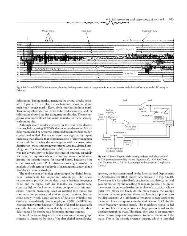
Fig. 6.6-9 Sample WWSSN seismogram, showing the long-period vertical component from an earthquake in the Indian Ocean, recorded 36° away in
Pakistan.
Fig. 6.6-10 Block diagram of the sensing and feedback electronics of
an IDA gravimeter recording system. (Agnew et al., 1976. Eos Trans.
Am. Geophys. Un., 57, 180–8, copyright by the American Geophysical
Union.)
calibration. Timing marks, generated by crystal clocks accurate to 1 part in 10 7 are placed at each minute (short mark) and
each hour (longer mark). Every sixth hour has no hour mark.
This timing allowed arrival times to be read accurately, and the
calibration allowed studies using true amplitudes. The seismograms were microfilmed and made available to the seismological community.
Although many results discussed in this text were derived
from such data, using WWSSN data was cumbersome. Microfiche records had be acquired, examined in a microfiche reader,
copied, and refiled. The traces were then digitized by taping
them to a special table that contained a grid of electromagnetic
wires and then tracing the seismogram with a cursor. After
digitization, the seismogram was interpolated to a desired sampling rate. The hand digitization added a source of error, as it
was not always easy to follow the trace of interest, especially
for large earthquakes where the surface waves could wrap
around the seismic record for several hours. Because of the
effort involved, entire Ph.D. dissertations might involve the
analysis of only tens or hundreds of seismograms, a task that is
now done in minutes to days.
The replacement of analog seismographs by digital broadband instruments has important advantages. The newer
seismometers provide better data over a broader frequency
band, and the digital data are available via magnetic tape,
compact disk, or the Internet, making computer analysis much
easier. Routine processing, such as rotating into radial and
transverse components and making record sections, has become nearly trivial. Large volumes of data are available and
can be processed easily. For example, as of 2000 the IRIS Data
Management Center had over 7 Tbytes of digital data available
over the Internet either immediately or with only the short
delay needed for it to be read from mass storage systems.
Some of the technology involved in more recent seismograph
systems is illustrated by one of the first digital seismological
systems, the instrument used by the International Deployment
of Accelerometers (IDA) shown schematically in Fig. 6.6-10.
The sensor is a force-feedback gravimeter that detects vertical
ground motion by the resulting change in gravity. The gravimeter mass is connected to the center plate of a capacitor whose
outer two plates are fixed. As the mass moves, the voltage
between the center plate and the outer plates is proportional to
the displacement. A 5 kilohertz alternating voltage applied to
the outer plates is amplitude-modulated (Section 2.8.1) by the
lower-frequency seismic signal. The modulated signal is fed
to an amplifier that generates a voltage proportional to the
displacement of the mass. This signal then goes to an integrator
circuit whose output is proportional to the acceleration of the
mass. This is the seismic system’s output, which is sampled
6.6 Seismometers and seismological networks 403
amplifier
5 k Hz drive
amplifier
Output
Openloop
output
Rack
Vault
Data
preamp
Center plate
Sensor and
forcing plates Splitterlinearizer
Inverting amp
Integrator
Closed-loop output
(feedback voltage)
Forcing
bias
Ref
Minute marks
m b = 5.6 M s = 5.2
Hour mark
Calibration pulse
Aftershocks
Fig. 6.6-9 Sample WWSSN seismogram, showing the long-period vertical component from an earthquake in the Indian Ocean, recorded 36° away in
Pakistan.
Fig. 6.6-10 Block diagram of the sensing and feedback electronics of
an IDA gravimeter recording system. (Agnew et al., 1976. Eos Trans.
Am. Geophys. Un., 57, 180–8, copyright by the American Geophysical
Union.)
calibration. Timing marks, generated by crystal clocks accurate to 1 part in 10 7 are placed at each minute (short mark) and
each hour (longer mark). Every sixth hour has no hour mark.
This timing allowed arrival times to be read accurately, and the
calibration allowed studies using true amplitudes. The seismograms were microfilmed and made available to the seismological community.
Although many results discussed in this text were derived
from such data, using WWSSN data was cumbersome. Microfiche records had be acquired, examined in a microfiche reader,
copied, and refiled. The traces were then digitized by taping
them to a special table that contained a grid of electromagnetic
wires and then tracing the seismogram with a cursor. After
digitization, the seismogram was interpolated to a desired sampling rate. The hand digitization added a source of error, as it
was not always easy to follow the trace of interest, especially
for large earthquakes where the surface waves could wrap
around the seismic record for several hours. Because of the
effort involved, entire Ph.D. dissertations might involve the
analysis of only tens or hundreds of seismograms, a task that is
now done in minutes to days.
The replacement of analog seismographs by digital broadband instruments has important advantages. The newer
seismometers provide better data over a broader frequency
band, and the digital data are available via magnetic tape,
compact disk, or the Internet, making computer analysis much
easier. Routine processing, such as rotating into radial and
transverse components and making record sections, has become nearly trivial. Large volumes of data are available and
can be processed easily. For example, as of 2000 the IRIS Data
Management Center had over 7 Tbytes of digital data available
over the Internet either immediately or with only the short
delay needed for it to be read from mass storage systems.
Some of the technology involved in more recent seismograph
systems is illustrated by one of the first digital seismological
systems, the instrument used by the International Deployment
of Accelerometers (IDA) shown schematically in Fig. 6.6-10.
The sensor is a force-feedback gravimeter that detects vertical
ground motion by the resulting change in gravity. The gravimeter mass is connected to the center plate of a capacitor whose
outer two plates are fixed. As the mass moves, the voltage
between the center plate and the outer plates is proportional to
the displacement. A 5 kilohertz alternating voltage applied to
the outer plates is amplitude-modulated (Section 2.8.1) by the
lower-frequency seismic signal. The modulated signal is fed
to an amplifier that generates a voltage proportional to the
displacement of the mass. This signal then goes to an integrator
circuit whose output is proportional to the acceleration of the
mass. This is the seismic system’s output, which is sampled
6.6 Seismometers and seismological networks 403