

254 Earthquakes
frequency of 5.2 GHz, so a fringe corresponds to 28 mm of
motion. The observed fringe pattern is coherent over large
areas where deformation is resolved. The pattern is reasonably similar to a synthetic interferogram (Fig. 4.5-3, bottom)
generated for a detailed model of the Landers rupture, which
involved several meters of right-lateral strike-slip on a complex
set of NW-striking faults extending for about 85 km.
InSAR has several attractive features for earthquake studies.
Although radar images before an earthquake are needed,
satellites can acquire them over areas far too large for geodetic
monuments to have been installed everywhere. In addition,
InSAR maps deformation on a spacing of tens of meters, far
denser than is practical with geodetic monuments. Moreover,
InSAR is especially sensitive to vertical motions, the component for which the GPS is the least precise. InSAR has several
limitations. It recovers motion only in the look direction. It
cannot be used in some areas of steep topography, where the
radar beam cannot penetrate, or where the slope facing the
radar is so steep that several points have the same range to
the radar. Another limitation is that nontectonic changes
between images, such as those due to vegetation growth or
weather conditions (which affect radio wave propagation in
the atmosphere), can mask the effects of crustal motion. However, when such decorrelation between successive images is not
a problem, as in deserts or other bare rock settings, InSAR is a
powerful tool. Finally, InSAR provides relative changes within
an image that is tens to a hundred kilometers across, but does
not provide absolute positions on a plate-wide or global scale.
This poses no problems for individual earthquake studies, but
means that it alone cannot be used for large-scale applications
like plate boundary studies. In many applications, InSAR and
GPS are both being combined with seismological data. These
techniques are also being applied together with seismology to
study ground deformation at volcanoes.
The advent of space-based methods like GPS and InSAR,
which make collecting geodetic data faster and easier, have
made earthquake geodesy and seismic wave studies common
overlapping approaches to earthquake studies. Hence, although
seismology and earthquake geodesy were long viewed as very
distinct, owing to their different instrumentation, earthquake
geodesy is increasingly viewed as very low-frequency seismology (or earthquake seismology as high-frequency geodesy).
4.5.2 Coseismic deformation
Seismic source theory shows that the static coseismic displacements produced by earthquakes have radiation patterns
analogous to the propagating wave displacements shown
in Fig. 4.2-6 and 4.2-7, and so can also provide important
information about the fault geometry and slip. An important
feature of these displacements is that they contain 1/r 2 terms,
compared to 1/r terms for the propagating waves (Eqns 1
and 2). Thus, compared to the propagating waves, the static
displacements decay more rapidly with distance from the
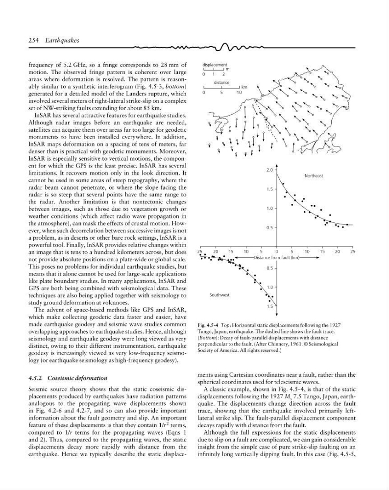
earthquake. Hence we typically describe the static displaceFig. 4.5-4 Top: Horizontal static displacements following the 1927
Tango, Japan, earthquake. The dashed line shows the fault trace.
(Bottom): Decay of fault-parallel displacements with distance
perpendicular to the fault. (After Chinnery, 1961. © Seismological
Society of America. All rights reserved.)
25
25
Northeast
2.0
1.5
1.0
0.5
20
15
10
5
0
5
1 0
15
20
Distance from fault (km)
0.5
1.0
1.5
Southwest
displacement
0
1
2
m
distance
0
5
1 0
km
ments using Cartesian coordinates near a fault, rather than the
spherical coordinates used for teleseismic waves.
A classic example, shown in Fig. 4.5-4, is that of the static
displacements following the 1927 M s 7.5 Tango, Japan, earthquake. The displacements change direction across the fault
trace, showing that the earthquake involved primarily leftlateral strike slip. The fault-parallel displacement component
decays rapidly with distance from the fault.
Although the full expressions for the static displacements
due to slip on a fault are complicated, we can gain considerable
insight from the simple case of pure strike-slip faulting on an
infinitely long vertically dipping fault. In this case (Fig. 4.5-5,
frequency of 5.2 GHz, so a fringe corresponds to 28 mm of
motion. The observed fringe pattern is coherent over large
areas where deformation is resolved. The pattern is reasonably similar to a synthetic interferogram (Fig. 4.5-3, bottom)
generated for a detailed model of the Landers rupture, which
involved several meters of right-lateral strike-slip on a complex
set of NW-striking faults extending for about 85 km.
InSAR has several attractive features for earthquake studies.
Although radar images before an earthquake are needed,
satellites can acquire them over areas far too large for geodetic
monuments to have been installed everywhere. In addition,
InSAR maps deformation on a spacing of tens of meters, far
denser than is practical with geodetic monuments. Moreover,
InSAR is especially sensitive to vertical motions, the component for which the GPS is the least precise. InSAR has several
limitations. It recovers motion only in the look direction. It
cannot be used in some areas of steep topography, where the
radar beam cannot penetrate, or where the slope facing the
radar is so steep that several points have the same range to
the radar. Another limitation is that nontectonic changes
between images, such as those due to vegetation growth or
weather conditions (which affect radio wave propagation in
the atmosphere), can mask the effects of crustal motion. However, when such decorrelation between successive images is not
a problem, as in deserts or other bare rock settings, InSAR is a
powerful tool. Finally, InSAR provides relative changes within
an image that is tens to a hundred kilometers across, but does
not provide absolute positions on a plate-wide or global scale.
This poses no problems for individual earthquake studies, but
means that it alone cannot be used for large-scale applications
like plate boundary studies. In many applications, InSAR and
GPS are both being combined with seismological data. These
techniques are also being applied together with seismology to
study ground deformation at volcanoes.
The advent of space-based methods like GPS and InSAR,
which make collecting geodetic data faster and easier, have
made earthquake geodesy and seismic wave studies common
overlapping approaches to earthquake studies. Hence, although
seismology and earthquake geodesy were long viewed as very
distinct, owing to their different instrumentation, earthquake
geodesy is increasingly viewed as very low-frequency seismology (or earthquake seismology as high-frequency geodesy).
4.5.2 Coseismic deformation
Seismic source theory shows that the static coseismic displacements produced by earthquakes have radiation patterns
analogous to the propagating wave displacements shown
in Fig. 4.2-6 and 4.2-7, and so can also provide important
information about the fault geometry and slip. An important
feature of these displacements is that they contain 1/r 2 terms,
compared to 1/r terms for the propagating waves (Eqns 1
and 2). Thus, compared to the propagating waves, the static
displacements decay more rapidly with distance from the
earthquake. Hence we typically describe the static displaceFig. 4.5-4 Top: Horizontal static displacements following the 1927
Tango, Japan, earthquake. The dashed line shows the fault trace.
(Bottom): Decay of fault-parallel displacements with distance
perpendicular to the fault. (After Chinnery, 1961. © Seismological
Society of America. All rights reserved.)
25
25
Northeast
2.0
1.5
1.0
0.5
20
15
10
5
0
5
1 0
15
20
Distance from fault (km)
0.5
1.0
1.5
Southwest
displacement
0
1
2
m
distance
0
5
1 0
km
ments using Cartesian coordinates near a fault, rather than the
spherical coordinates used for teleseismic waves.
A classic example, shown in Fig. 4.5-4, is that of the static
displacements following the 1927 M s 7.5 Tango, Japan, earthquake. The displacements change direction across the fault
trace, showing that the earthquake involved primarily leftlateral strike slip. The fault-parallel displacement component
decays rapidly with distance from the fault.
Although the full expressions for the static displacements
due to slip on a fault are complicated, we can gain considerable
insight from the simple case of pure strike-slip faulting on an
infinitely long vertically dipping fault. In this case (Fig. 4.5-5,