

4.3 Waveform modeling 233
0
N
E
Thrust fault
pP
sP
P
Side view of
focal sphere
N
E
Vertical dip–slip
pP
sP
P
Side view of
focal sphere
10
20
30
40
50
Time (s)
sP
pP
P
0
10
20
30
40
50
Time (s)
sP
pP
P
and those for SH waves are
p L = sin λ sin δ cos δ sin 2(φ f − φ) + cos λ sin δ cos 2(φ f − φ),
q L = −cos λ cos δ sin (φ f − φ) + sin λ cos 2δ cos (φ f − φ).
(14)
The reflected phases’ amplitudes also include the plane wave
potential reflection coefficients at the free surface, Π PP (i h ) and
Π SP (j h ), which depend on the angles of incidence. Finally, the
sP term is scaled by a factor (α h cos i h )/(β h cos j h ) which incorporates several effects, including the fact that near the source
the wave incident on the surface is better treated as a spherical
wave than a plane wave.
We could similarly model the SH wave, which arrives much
later, by summing direct S and sS using an expression analogous to Eqn 12, with the S-wave velocity, take-off angles, delay
times, and the SH-wave radiation pattern R SH .
This formulation shows how synthetic body wave seismograms depend on the assumed focal depth, which determines
the time separation between arrivals, the mechanism, which
determines the relative amplitudes of the arrivals, and the
the travel time for that ray, τ P , τ pP , and τ sP . Each arrival’s
amplitude depends on the body wave radiation pattern at the
source for that wave type
R P (φ, i) = s R (3 cos 2 i − 1) − q R sin 2i − p R sin 2 i,
R SV (φ, j) =
3
2
s R sin 2j + q R cos 2j +
1
2
p R sin 2j,
R SH (φ, j) = −q L cos j − p L sin j,
(13)
which depend on the take-off angle (i for P waves and j for
S waves) and a set of fault geometry factors which include
the fault strike, dip and slip angles (Fig. 4.2-2) φ f , δ, λ, and the
azimuth φ (clockwise from north) to the station. For P − SV
waves these factors are
s R = sin λ sin δ cos δ,
q R = sin λ cos 2δ sin (φ f − φ) + cos λ cos δ cos (φ f − φ),
p R = cos λ sin δ sin 2(φ f − φ) − sin λ sin δ cos δ cos 2(φ f − φ),
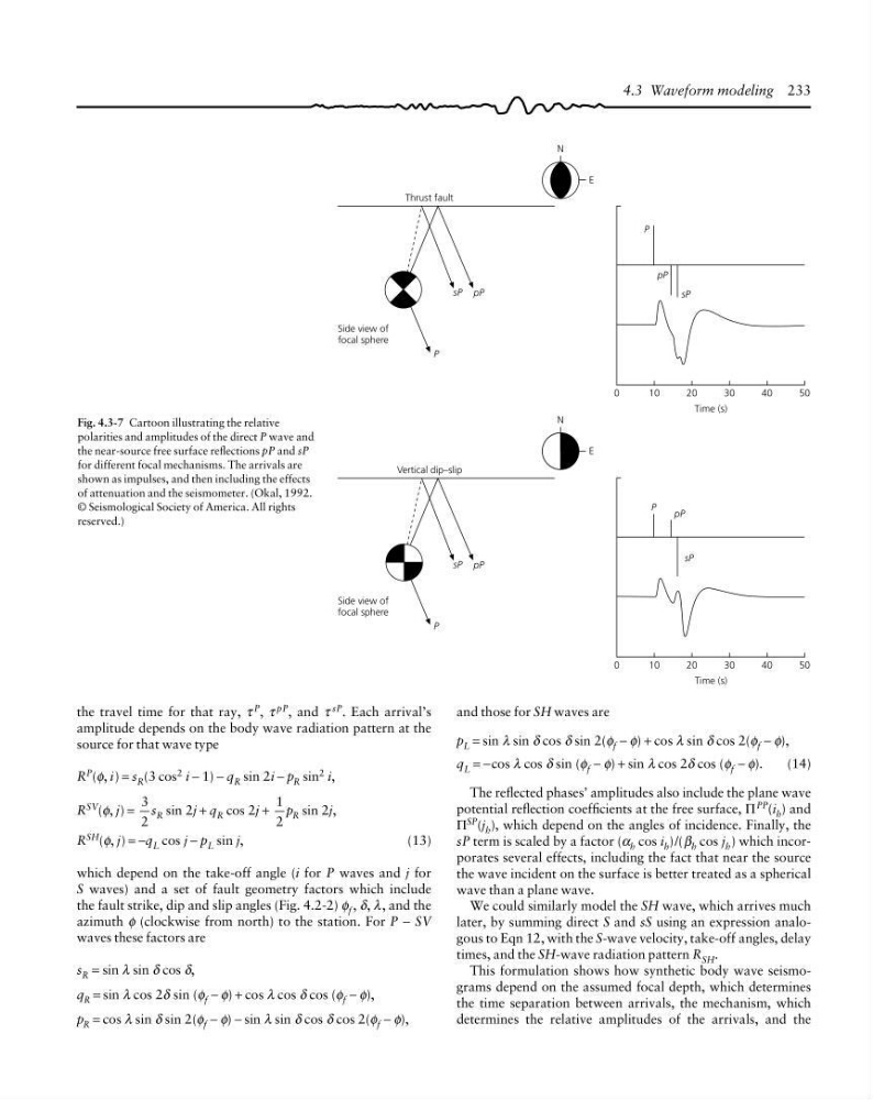
Fig. 4.3-7 Cartoon illustrating the relative
polarities and amplitudes of the direct P wave and
the near-source free surface reflections pP and sP
for different focal mechanisms. The arrivals are
shown as impulses, and then including the effects
of attenuation and the seismometer. (Okal, 1992.
© Seismological Society of America. All rights
reserved.)
0
N
E
Thrust fault
pP
sP
P
Side view of
focal sphere
N
E
Vertical dip–slip
pP
sP
P
Side view of
focal sphere
10
20
30
40
50
Time (s)
sP
pP
P
0
10
20
30
40
50
Time (s)
sP
pP
P
and those for SH waves are
p L = sin λ sin δ cos δ sin 2(φ f − φ) + cos λ sin δ cos 2(φ f − φ),
q L = −cos λ cos δ sin (φ f − φ) + sin λ cos 2δ cos (φ f − φ).
(14)
The reflected phases’ amplitudes also include the plane wave
potential reflection coefficients at the free surface, Π PP (i h ) and
Π SP (j h ), which depend on the angles of incidence. Finally, the
sP term is scaled by a factor (α h cos i h )/(β h cos j h ) which incorporates several effects, including the fact that near the source
the wave incident on the surface is better treated as a spherical
wave than a plane wave.
We could similarly model the SH wave, which arrives much
later, by summing direct S and sS using an expression analogous to Eqn 12, with the S-wave velocity, take-off angles, delay
times, and the SH-wave radiation pattern R SH .
This formulation shows how synthetic body wave seismograms depend on the assumed focal depth, which determines
the time separation between arrivals, the mechanism, which
determines the relative amplitudes of the arrivals, and the
the travel time for that ray, τ P , τ pP , and τ sP . Each arrival’s
amplitude depends on the body wave radiation pattern at the
source for that wave type
R P (φ, i) = s R (3 cos 2 i − 1) − q R sin 2i − p R sin 2 i,
R SV (φ, j) =
3
2
s R sin 2j + q R cos 2j +
1
2
p R sin 2j,
R SH (φ, j) = −q L cos j − p L sin j,
(13)
which depend on the take-off angle (i for P waves and j for
S waves) and a set of fault geometry factors which include
the fault strike, dip and slip angles (Fig. 4.2-2) φ f , δ, λ, and the
azimuth φ (clockwise from north) to the station. For P − SV
waves these factors are
s R = sin λ sin δ cos δ,
q R = sin λ cos 2δ sin (φ f − φ) + cos λ cos δ cos (φ f − φ),
p R = cos λ sin δ sin 2(φ f − φ) − sin λ sin δ cos δ cos 2(φ f − φ),
Fig. 4.3-7 Cartoon illustrating the relative
polarities and amplitudes of the direct P wave and
the near-source free surface reflections pP and sP
for different focal mechanisms. The arrivals are
shown as impulses, and then including the effects
of attenuation and the seismometer. (Okal, 1992.
© Seismological Society of America. All rights
reserved.)