

4.2 Focal mechanisms 225
S
N
S
N
1 0 °
2 0 °
30 ° 40°
60°
Take-off
angle
30°
Dip
R o ta te
R e tu r n
Azimuth = 40°
Take-off angle = 60°
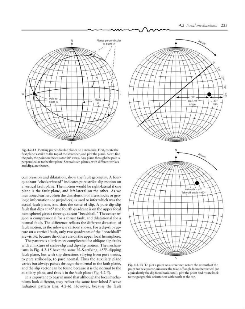
Fig. 4.2-13 To plot a point on a stereonet, rotate the azimuth of the
point to the equator, measure the take-off angle from the vertical (or
equivalently the dip from horizontal), plot the point and rotate back
to the geographic orientation with north at the top.
Fig. 4.2-12 Plotting perpendicular planes on a stereonet. First, rotate the
first plane’s strike to the top of the stereonet, and plot the plane. Next, find
the pole, the point on the equator 90° away. Any plane through the pole is
perpendicular to the first plane. Several such planes, with different strikes
and dips, are shown.
W
E
N
S
Planes perpendicular
to plane A
Pole to
plane A
Plane
A
compression and dilatation, show the fault geometry. A fourquadrant “checkerboard” indicates pure strike-slip motion on
a vertical fault plane. The motion would be right-lateral if one
plane is the fault plane, and left-lateral on the other. As we
mentioned earlier, often the distribution of aftershocks or geologic information (or prejudices) is used to infer which was the
actual fault plane, and thus the sense of slip. A pure dip-slip
fault that dips at 45° (the fourth quadrant is on the upper focal
hemisphere) gives a three-quadrant “beachball.” The center region is compressional for a thrust fault, and dilatational for a
normal fault. The difference reflects the different direction of
fault motion, as the side-view cartoon shows. For a dip-slip rupture on a vertical fault, only two quadrants of the “beachball”
are visible, because the others are on the upper focal hemisphere.
The pattern is a little more complicated for oblique-slip faults
with a mixture of strike-slip and dip-slip motion. The mechanisms in Fig. 4.2-15 have the same N–S-striking, 45°E-dipping
fault plane, but with slip directions varying from pure thrust,
to pure strike-slip, to pure normal. Thus the auxiliary plane
varies but always passes through the normal to the fault plane,
and the slip vector can be found because it is the normal to the
auxiliary plane, and thus is in the fault plane (Fig. 4.2-5).
It is important to bear in mind that although the focal mechanisms look different, they reflect the same four-lobed P-wave
radiation pattern (Fig. 4.2-6). However, because the fault
S
N
S
N
1 0 °
2 0 °
30 ° 40°
60°
Take-off
angle
30°
Dip
R o ta te
R e tu r n
Azimuth = 40°
Take-off angle = 60°
Fig. 4.2-13 To plot a point on a stereonet, rotate the azimuth of the
point to the equator, measure the take-off angle from the vertical (or
equivalently the dip from horizontal), plot the point and rotate back
to the geographic orientation with north at the top.
Fig. 4.2-12 Plotting perpendicular planes on a stereonet. First, rotate the
first plane’s strike to the top of the stereonet, and plot the plane. Next, find
the pole, the point on the equator 90° away. Any plane through the pole is
perpendicular to the first plane. Several such planes, with different strikes
and dips, are shown.
W
E
N
S
Planes perpendicular
to plane A
Pole to
plane A
Plane
A
compression and dilatation, show the fault geometry. A fourquadrant “checkerboard” indicates pure strike-slip motion on
a vertical fault plane. The motion would be right-lateral if one
plane is the fault plane, and left-lateral on the other. As we
mentioned earlier, often the distribution of aftershocks or geologic information (or prejudices) is used to infer which was the
actual fault plane, and thus the sense of slip. A pure dip-slip
fault that dips at 45° (the fourth quadrant is on the upper focal
hemisphere) gives a three-quadrant “beachball.” The center region is compressional for a thrust fault, and dilatational for a
normal fault. The difference reflects the different direction of
fault motion, as the side-view cartoon shows. For a dip-slip rupture on a vertical fault, only two quadrants of the “beachball”
are visible, because the others are on the upper focal hemisphere.
The pattern is a little more complicated for oblique-slip faults
with a mixture of strike-slip and dip-slip motion. The mechanisms in Fig. 4.2-15 have the same N–S-striking, 45°E-dipping
fault plane, but with slip directions varying from pure thrust,
to pure strike-slip, to pure normal. Thus the auxiliary plane
varies but always passes through the normal to the fault plane,
and the slip vector can be found because it is the normal to the
auxiliary plane, and thus is in the fault plane (Fig. 4.2-5).
It is important to bear in mind that although the focal mechanisms look different, they reflect the same four-lobed P-wave
radiation pattern (Fig. 4.2-6). However, because the fault