

4.2 Focal mechanisms 219
Left-lateral strike-slip fault
( = 0°)
λ
Right-lateral strike-slip fault
( = 180°)
λ
Reverse dip-slip fault
( = 90°)
λ
Normal dip-slip fault
( = –90°)
λ
”Up”
Fault plane
Dilatation
Compression
Epicenter
Dilatation
Compression
Auxiliary
plane
“Down”
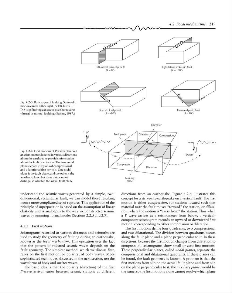
Fig. 4.2-4 First motions of P waves observed
at seismometers located in various directions
about the earthquake provide information
about the fault orientation. The two nodal
planes separate regions of compressional
and dilatational first arrivals. One nodal
plane is the fault plane, and the other is the
auxiliary plane, but these data cannot
distinguish which is the actual fault plane.
Fig. 4.2-3 Basic types of faulting. Strike-slip
motion can be either right- or left-lateral.
Dip-slip faulting can occur as either reverse
(thrust) or normal faulting. (Eakins, 1987.)
directions from an earthquake. Figure 4.2-4 illustrates this
concept for a strike-slip earthquake on a vertical fault. The first
motion is either compression, for stations located such that
material near the fault moves “toward” the station, or dilatation, where the motion is “away from” the station. Thus when
a P wave arrives at a seismometer from below, a verticalcomponent seismogram records an upward or downward first
motion, corresponding to either compression or dilatation.
The first motions define four quadrants, two compressional
and two dilatational. The division between quadrants occurs
along the fault plane and a plane perpendicular to it. In these
directions, because the first motion changes from dilatation to
compression, seismograms show small or zero first motions.
These perpendicular planes, called nodal planes, separate the
compressional and dilatational quadrants. If these planes can
be found, the fault geometry is known. A problem is that the
first motions from slip on the actual fault plane and from slip
on the plane perpendicular to it, the auxiliary plane, would be
the same, so the first motions alone cannot resolve which plane
understand the seismic waves generated by a simple, twodimensional, rectangular fault, we can model those resulting
from a more complicated set of ruptures. This application of the
principle of superposition is based on the assumption of linear
elasticity and is analogous to the way we constructed seismic
waves by summing normal modes (Sections 2.2.5 and 2.9).
4.2.2 First motions
Seismograms recorded at various distances and azimuths are
used to study the geometry of faulting during an earthquake,
known as the focal mechanism. This operation uses the fact
that the pattern of radiated seismic waves depends on the
fault geometry. The simplest method, which we discuss first,
relies on the first motion, or polarity, of body waves. More
sophisticated techniques, discussed in the next section, use the
waveforms of body and surface waves.
The basic idea is that the polarity (direction) of the first
P-wave arrival varies between seismic stations at different
Left-lateral strike-slip fault
( = 0°)
λ
Right-lateral strike-slip fault
( = 180°)
λ
Reverse dip-slip fault
( = 90°)
λ
Normal dip-slip fault
( = –90°)
λ
”Up”
Fault plane
Dilatation
Compression
Epicenter
Dilatation
Compression
Auxiliary
plane
“Down”
Fig. 4.2-4 First motions of P waves observed
at seismometers located in various directions
about the earthquake provide information
about the fault orientation. The two nodal
planes separate regions of compressional
and dilatational first arrivals. One nodal
plane is the fault plane, and the other is the
auxiliary plane, but these data cannot
distinguish which is the actual fault plane.
Fig. 4.2-3 Basic types of faulting. Strike-slip
motion can be either right- or left-lateral.
Dip-slip faulting can occur as either reverse
(thrust) or normal faulting. (Eakins, 1987.)
directions from an earthquake. Figure 4.2-4 illustrates this
concept for a strike-slip earthquake on a vertical fault. The first
motion is either compression, for stations located such that
material near the fault moves “toward” the station, or dilatation, where the motion is “away from” the station. Thus when
a P wave arrives at a seismometer from below, a verticalcomponent seismogram records an upward or downward first
motion, corresponding to either compression or dilatation.
The first motions define four quadrants, two compressional
and two dilatational. The division between quadrants occurs
along the fault plane and a plane perpendicular to it. In these
directions, because the first motion changes from dilatation to
compression, seismograms show small or zero first motions.
These perpendicular planes, called nodal planes, separate the
compressional and dilatational quadrants. If these planes can
be found, the fault geometry is known. A problem is that the
first motions from slip on the actual fault plane and from slip
on the plane perpendicular to it, the auxiliary plane, would be
the same, so the first motions alone cannot resolve which plane
understand the seismic waves generated by a simple, twodimensional, rectangular fault, we can model those resulting
from a more complicated set of ruptures. This application of the
principle of superposition is based on the assumption of linear
elasticity and is analogous to the way we constructed seismic
waves by summing normal modes (Sections 2.2.5 and 2.9).
4.2.2 First motions
Seismograms recorded at various distances and azimuths are
used to study the geometry of faulting during an earthquake,
known as the focal mechanism. This operation uses the fact
that the pattern of radiated seismic waves depends on the
fault geometry. The simplest method, which we discuss first,
relies on the first motion, or polarity, of body waves. More
sophisticated techniques, discussed in the next section, use the
waveforms of body and surface waves.
The basic idea is that the polarity (direction) of the first
P-wave arrival varies between seismic stations at different